This thread has been locked.

If you have a related question, please click the "Ask a related question" button in the top right corner. The newly created question will be automatically linked to this question.

TLC2264: Input offset voltage

Part Number: TLC2264
Other Parts Discussed in Thread: TLC2262, TL032A, TLC277, TL052A, OP07D, TLE2027

Hi team,

Could you please help us for following 2 questions?

I referred to the page, https://e2e.ti.com/blogs_/archives/b/precisionhub/posts/ic-long-term-stability-the-only-constant-is-change.

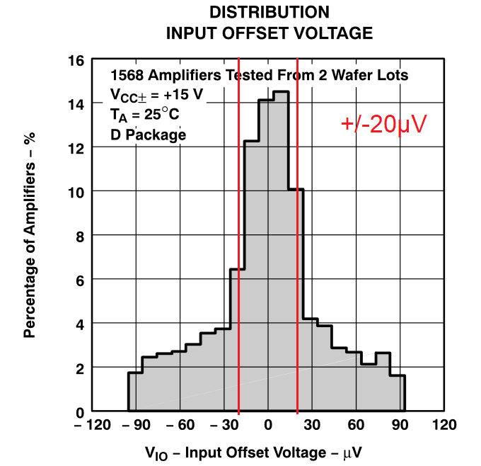
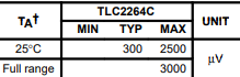
1. Typical value of Vio is shown 300uV in 25C.
Does it mean it is ±1σ and around 68% products is within this range?

2. Can we know rough rating that reaches around Max value, 2500uV for this product?

Best regards,

Yuto

  • Hey Yuto-san,

    Our current practice is to assign the typical value as the 1σ value, I'm uncertain if this was the practice used when creating the TLC2264C's datasheet, but you may use it as a rule of thumb.

    The max value is a tested limit. The parts are screened at time of manufacture and will not exceed that value. You may statistically estimate the value using the 1σ value, it would be an 8.3σ value, which is a very small percentage of parts.

    Best,
    Jerry

  • Hi,

    On page 31 of the datasheet you can see the distribution of the Vio. Indeed, 300uV appears as the standard deviation, as Jerry said.

    Best wishes, Zoltan

  • Hi Yuto,

    the 300µV typical input offset voltage seems to fit well with the input offset voltage distribution of TLC2262 shown in figure 3 of datasheet. But this distribution is gained from only two wafers and not from the whole production. And it doesn't tell anything about the distributions seen on other wafers or wafers from other production plants. It's not even clear that the distributions of all wafers are true Gaussian distributions. So I would be vary wary in assuimg that the 300µV typical specification is the ±1σ of all fabricated TLC2262. When the maximum input offset voltage can be 8.3 times higher than the typical value, then this cannot be explained with the nice distribution shown in figure 3.

    Many input offset voltage distributions of OPAmps are not true Gaussian distributions. See the datasheets of TL032A, TL052A, TLC277, OP07D (ADI) or LT1006 (ADI), for instance.

    The datasheet of TLE2027 shows this distribution which doesn't look true Gaussian either:

    The typical input offset voltage specification is 20µV and the maximum specification is 100µV. But a careful estimation of the total area under the curve and the area between the two red 20µV limits returns the result that only 51% of all TLE2027 are within the 20µV limits. This is far away from ±1σ = 68%.

    Don't understand me wrong. I don't critisize that the distributions are not true Gaussian. Just the opposite. I do not trust a published distribution curve which looks all too nice and all too Gaussian. A true Gaussian distribution curve would mean an ideal situation but real life is not ideal. The distribution of TLE2027 looks very realistic and plausible in my eyes. It demonstrates that you can have a lot of OPAmps in your circuit clearly exceeding the +/-20µV typical input offset voltage.

    As being a professional circuit designer, I'm not interested in any typical input offset voltage specification either. I have to design the circuit such robust that it will work even with the specified maximum input offset voltage. But I have never understood why a so tiny typical input offset voltage is given in so many datasheets and from so many manufacturers when the maximum value can be ten times or more higher.

    Kai 

  • Hi Kai,

    I’ve enjoyed reading your inspiring and very informative post. Just let me go a bit further and have a related question.

    I agree with you, that if the offset voltage is critical then the guaranteed limit should be considered. However, if a typical value is enough for a design (e.g. in audio or other AC applications), then having 51% or 68% within typical spec and the shape of the distribution doesn’t really matter, it is not really important if the scattering follows normal distribution closely. In such cases I think you can rely on typical values safely. You don’t have to assume that the limits can be orders of magnitude larger than the typical values (unless the datasheet says something else, which occurs very rarely I think). As a rule of thumb, the approximately 2/3 within the typical value can work as accurately as needed, I think. Of course, you should not use this to estimate a “guaranteed limit” when it is absent. Also, in certain cases you may have the possibility to implement some kind of calibration or offset voltage. measurement. The extremes can be screened out too (as Jerry mentined for the opamps) and it can be economical if the proportion is small enough.

    I agree that the distribution is not necessarily a normal distribution. One reason can be that different manufacturing processes can mean different average offset voltage. Combining these can result in such a histogram that one can see in the datasheet of LT1006 you’ve mentioned.

    In addition, the histogram frequently based on a relatively small amount of samples, many of the bins often contain less than 10 samples, so one can’t say too much about the distribution.

    Since practically all of the datasheets contain certain parameters with typical values only, in other words, guaranteed limits are missing for these (the gain-bandwidth-product or phase margin could be such, page 7 of the TLC2264 datasheet has several additional examples)  how a designer should handle these? What should the margin for the design if only a typical value is konwn? I would be grateful if I could see the answer of a professional designer.

    Best wishes, Zoltan

  • Hi Zoltan,

    there's no simple answer. It heavily depends on the application. I usually take an OPAmp that has lots of headroom in the critical parameter. Then a missing maximum specification does not harm. If no such OPAmp is available, I choose an OPAmp which has a maximum specification in the datasheet.

    In any case, I carry out very thorough testings with the real world circuit to find out whether the chip and the datasheet are trustworthy. Many issues are not documented in the datasheet and you must always be prepared for a surprise. This the more the more exotic the OPAmp is.

    Because the testings are extremely time consuming, I tend to use an OPAmp once found trustworthy, even if there might be a better OPAmp available for a certain application.

    This might interest you:

    https://e2e.ti.com/blogs_/archives/b/precisionhub/posts/ic-long-term-stability-the-only-constant-is-change

    Kai

  • Hi Kai,

    Thanks a lot!

    Zoltan