This thread has been locked.

If you have a related question, please click the "Ask a related question" button in the top right corner. The newly created question will be automatically linked to this question.

OPA548: Small high frequency sine signals gets added to the output

Part Number: OPA548

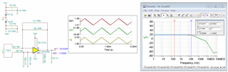
I am trying to design a non-inverting amplifier similar to the one given in Fig 26 of https://www.ti.com/lit/ds/symlink/opa548.pdf.

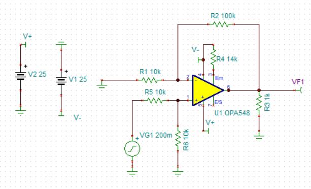
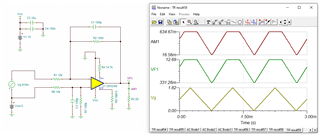
This is the circuit diagram. The input is a ramp signal with high voltage 3 V and low signal 0.2 Vp-p and frequency 1 kHz. 

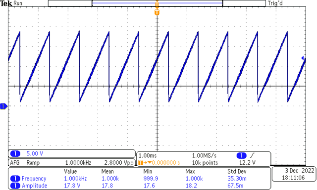
I am getting the expected output. 

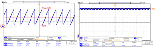
But if I zoom into the signal, I also see a sine signal of frequency around 10 MHz and amplitude 0.7 Vp-p added to the output.

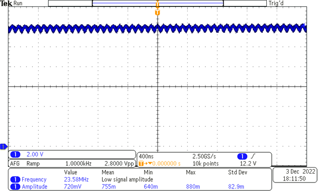
What could be the cause and how to get rid of it?

  • Hi Kishore,

    this can have many reasons:

    1. Don't touch the output of OPAmp directly with the scope probe or multimeter, but insert an isolation resistor of 100...200R first.

    2. I hope you don't have connected a capacitive load to the output of OPAmp? Your schematic doesn't show any.

    3. The noise can come from the supply rails. Have you generated the supply voltage by the help of a switching regulator? Scope the supply voltages in AC mode and show the scope plots.

    4. I do not see any supply voltage decoupling caps in your circuit. Add them according to figure 25 of datasheet.

    5. Don't use any cabling at the inputs and outputs of OPAmp. Avoid using a breadboard.

    6. The HF-noise can already come from the input. Try a small low pass filtering cap in parallel to R6. Scope the input signal and show the scope plot.

    7. It's always wise to have a phase lead capacitance in the feedback loop. Mount a small cap in parallel to R2.

    Please show a photo of your setup and the layout of your circuit.

    Kai

  • Hi Kishore,

    The input is a ramp signal with high voltage 3 V and low signal 0.2 Vp-p and frequency 1 kHz.

    As Kai pointed out, it is not clear what are the root causes. Please follow Kai's suggestions to check the circuit's setup. 

    I simulated your described condition. The difference amplifier has a gain of 10V/V. I extracted the input voltage from the scope shot, it looks like the simulation below, where Vin is approx. 0.91V ± 0.91Vpp @1kHz, see the simulation. 

    OPA548 Diff Amp 12052022.TSC

    Two scope shots have two different output voltage profiles. The 1st plot is closed to what is simulated, but the 2nd plot is centered at approx. 12Vdc with AC signal riding on it. I do not know why it is different. Please make sure that you do not have capacitive load at the output of the power amplifier. Otherwise, it may require some kind of op amp loop compensation. 

    Please use short ground leads to measure the output signal. 

    If you have additional questions, please let us know. 

    Best,

    Raymond

  • Thank you kai and Raymond for your suggestions. 

    I have connected not connected any capacitive load in the output.

    I am not using switching regulators for power rails.  And have not used any capacitors at all. 

    I would like to design a PCB to use the op amp. But to verify if it works as expected I am currently trying it in a breadboard. Look like breadboard, DSO probe wires and input wires all lead to noise. 

    But the final schematic that I prefer to use is non inverting amplifier with single rail power (0 to 30 V). When I tried single rail configuration I noticed the output saturates to (V+)-1.4 V.  I tried increasing my V+ from 0 to 15 V. It appeared like it is saturating in open loop configuration.

    I believe that's because of my cluttered setup arrangement in breadboard. Hopefully the IC would perform better in a PCB. Or is there any other reason for such saturating output?

  • Hi Kishore,

    It is not clear what is the V+ voltage rail and load value. 

    For a single power supply rail, please make sure that your input Vcm meets OPA548's input voltage requirements, and Vout voltage swing is a function of load current, see the attached simulation capture. 

    If V+ = 15Vdc is used as a single supply configuration, the Vout will saturate per the simulated conditions below.   

    If you have additional questions, please let us know. 

    Best,

    Raymond