A related question is a question created from another question. When the related question is created, it will be automatically linked to the original question.
If you have a related question, please click the "Ask a related question" button in the top right corner. The newly created question will be automatically linked to this question.
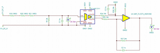
My only comment is that the 1u filter capacitors, C1, C2, C3 set a very low cutoff frequency and smaller values could be considered. Analog filtering is often most effective to help remove high frequency signals that may alias into the sampling range whereas for lower frequency noise, it's often best to rely on the common-mode rejection ratio of the differential input. This is due to potential tolerance mismatches between large capacitors such as C2 and C3, that may filter the signal differently and actually create a differential voltage between the positive and negative output. The single-ended output of the amplifier should be placed as close as possible to the input of the ADC to minimize noise that may couple to the signal line.
Correct. Most caps will have +/-10%-15% variation (+more over temperature). With larger capacitance values, there will be more variation in the cutoff frequency 1/(2*pi*R*C). I would suggest values that set the cutoff to be at least 10x the signal frequency of interest and less than 2MHz but it also depends on what noise sources are in the system. These values can be debugged once the board is in the testing phase, but reducing to 10pF for C1 and 1nF for C2/3 are good starting points.