This thread has been locked.

If you have a related question, please click the "Ask a related question" button in the top right corner. The newly created question will be automatically linked to this question.

INA129: Amplifiers forum

Part Number: INA129
Other Parts Discussed in Thread: REF3312, , REF3325, REF5025

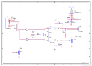
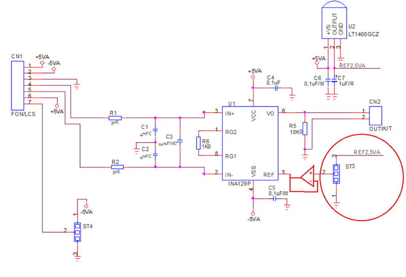
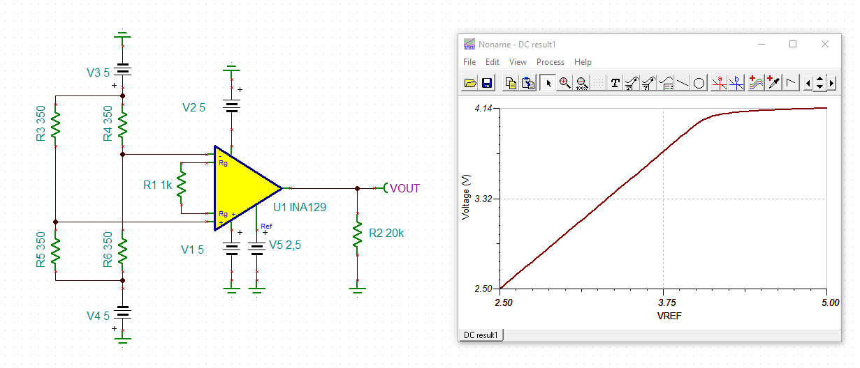
Tenho um circuito que utiliza o Amplificador de Precisão INA129P, quando utilizando o modelo INA129PA, a saída do mesmo apresenta-se próxima da tensão V+. O ganho do circuito é 50, fonte V+ (+5V) V- (-5V), Ref. 0V, Vin (0-20mV medição de Célula de Carga). Questão: circuito funciona correto para INA129P e não funciona com INA129PA, alguém tem uma dica.


  • Bridge; 350 ohms; +Exc (+5V) e -Exc (-5V); tipo strain gauge utilizadas em balanças; sensibilidade 2,0mV/V

  • Tarciso,

    The main difference between INA129P and INA129PA is the maximum input offset voltage and input bias current.  The INA129PA maximum offset voltage for G=50 would be +/-145uV, resulting in +/-7.25mA error at the output, which would not account for the output being at the +5V rail.

    Ios of +/-10nA across 350 ohm would also not cause the error of several volts - see below.

    No entanto, você diz que usa Vref de 0V, mas seu esquema mostra o pino de referência de acionamento do divisor resistivo. Vref DEVE ser de baixa impedância para funcionar corretamente e, portanto, DEVE ser armazenado em buffer conforme mostrado abaixo. Aliás, se precisar de Vref de 1,25V, pode usar REF3312.

  • Bom dia, Marek.

    Primeiramente, desculpe não ter cumprimentado você no Reply anterior.

    Em relação ao sinal de REF, não há divisor e sim um jumper programável que posso selecionar 0V ou 2,5V para outra aplicação.

    Se entendi, no seu Reply o circuito não modifica para P ou PA, as características diferentes entre eles produziriam valores de saída com pequena alteração e não mantendo a saída próxima de V+ . O que nos leva a saber que o componente testado pode estar com problema.

    Obrigado pelo suporte Marek.

  • Hi Tarciso,

    the problem here could be that the LT1460 can only emit current at its output but not absorb. Or by other words, that the LT1460 is not bidirectional at its output. When the LT1460 shall absorb current, its output voltage may rise and by this the output voltage of INA129:

    A good remedy then is to insert a buffer, as Marek showed, which can not only emit current but also absorb.

    Kai 

  • With Vref grounded, there should be no issue driving the Vref pin. Thus, I wonder what do you use for -5VA that could cause the problem you see (other than the possibility that the part is damaged)?  Having said that, your circuit will NOT work with LT1650-2.5 because as Kai suggested INA129 reference pin requires sourcing and sinking capability while LT1650-2.5 can only source the current like LDO. Thus, you either need to add the buffer as shown above or use another part like REF3325 with sinking/sourcing Iout of +/-5mA or higher precision REF5025 with Iout of +/-10mA.