This thread has been locked.

If you have a related question, please click the "Ask a related question" button in the top right corner. The newly created question will be automatically linked to this question.

INA229-Q1: INA229 VBUS sampling accuracy problem

Part Number: INA229-Q1
Other Parts Discussed in Thread: INA129, INA229

Hi expert,

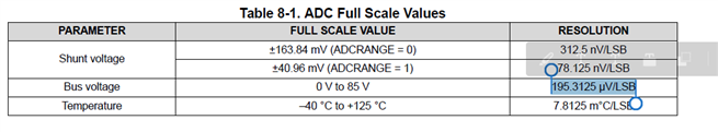
We need to use VBUS for insulation impedance detection. The minimum voltage may be about 2mV. Could you help me confirm that the accuracy of Vbus can meet the requirements? We will add partial voltage ratio externally, and adjust 200~1000V to 0~85V, how should I use the following parameters to evaluate the accuracy? thanks.

  • Hi Hangje,

    this is how I would read the datasheet:

    The offset voltage is up to +/-2.5mV, according to +/-13LSB. The offset voltage is specified at a very low bus voltage to prevent the offset voltage from being influenced by the gain error.

    The gain error is +/-0.05% referring to +85V full scale bus voltage, which translates to an error voltage of +/-42.5mV at full scale, according to +/-218LSB.

    If you want to install a voltage divider at the bus voltage input, you must additionally consider the input resistance of INA129 which is 1MOhm with a tolerance of +/-20%. So, your input voltage divider (the leg to GND) should be way more low ohmic compared to 1M to scale this tolerance down to a suited value.

    You must also consider the input bias current of up to 2.5nA, which will flow through your input voltage divider and cause an additional input offset voltage.

    What input voltage divider are you planning to use?

    It could be wise to perform some sort of software calibration of your whole circuit to calibrate out the error coming from the input voltage divider and to enhance the overall precision.

    Kai

  • Hey Hangjie,

    In addition to what Kai said, if you scale down the VBUS voltage you will need to account for that in the results values that rely on a bus measurement. Also, for maximum VBUS accuracy, you'll want to increase the conversion time and number of averages. 

    Regards,

    Mitch

  • Hi kai, Mitch,

    Thanks for your quick reply.  If I only test the 0~2.5V voltage, do you think amplifying the 0~2.5V voltage to 0~85V will help the accuracy? What should be paid attention to when designing? 

    Can ALERT be configured as OC protection only, output logic level to cooperate with external circuit to realize hardware protection.

  • Hey Hangjie,

    Here are my responses to your questions:

    Thanks for your quick reply.  If I only test the 0~2.5V voltage, do you think amplifying the 0~2.5V voltage to 0~85V will help the accuracy? What should be paid attention to when designing? 

    No, I do not think amplifying the voltage would be a good idea. Anytime you change the voltage level, you introduce the potential to add error. As for things to pay attention to, here is a link to a video series that I think would be helpful: https://training.ti.com/ti-precision-labs-current-sense-amplifiers

    Can ALERT be configured as OC protection only, output logic level to cooperate with external circuit to realize hardware protection.

    Yes it can.

    Regards,

    Mitch

  • Hi Mitch,

    How should I implement it by configuring register Diag_ALRT? I found out that I can't disable other protection functions except SHNTOL, Or do I need to set other fault comparison values ​​to the maximum to avoid alert reporting OC faults instead of other faults? Is there a potential risk in doing so? Because this will cause the system to trigger a power down due to unexpected faults.

    Looking forward to your reply, thanks.

  • Hey Hangjie,

    The default values in the threshold registers are essentially disabled. These values default to max (or min for under threshold), and the alert will only trigger if the value is exceeded (which can't happen when the values are at max (or min for under threshold)). So, you don't need to do anything to disable the other thresholds, just put a limit value in for the threshold register you want, and it will trigger when exceeded. 

    Regards,

    Mitch

  • Hi Mitch,

    Thank so much for your timely reply.

    According to your description, I understand that INA229 compares the actual value with the value of the comparison register. If the threshold is exceeded, the Alert will output the corresponding logic level.

    And you mentioned that the default configuration is the maximum or minimum value, and this is the root cause of the inability to trigger the protection. Can this be equivalent to the disable logic?

    Since this is used in BMS, it involves the safety of the user, pls help to confirm the following questions again:
    1. If I use ALERT to control the disconnection of the circuit, can we guarantee that the logic state on the alert will never change when customer don't configure any threshold registers?


    2. Does INA229 itself trigger over-temperature protection, for example, when the temperature reaches 160°C, will it affect the output of ALERT?

    3.If the maximum or minimum value can be equivalent to the disable of SHNTUL, SHNTOL, BUSOL, BUSUL, TMPOL, POL, is it because no value will exceed the threshold? Does the presence of noise in the system affect this?

    Best regards

  • Hello Hangjie,

    Here are my responses to your questions:

    And you mentioned that the default configuration is the maximum or minimum value, and this is the root cause of the inability to trigger the protection. Can this be equivalent to the disable logic?

    Yes, this is equivalent to disabling the alert. 

    1. Yes, the ALERT pin will never trigger for alert thresholds that are not configured. It also wont change for conversion ready unless that is configured as well.

    2. No, it will only trigger on temperature alerts if they are configured in the limit registers.

    3. Correct, this is because the threshold value is compared to the measured value, and the measured value cannot exceed the register size. So, noise will not affect it, because even if there is noise that goes above the measurable range of a register the measured value will still be capped at the maximum register size. The alert will not trip unless the measured value exceeds the threshold value, so when the threshold value is at max/min, then the measured value cannot exceed that.

    Regards,

    Mitch