This thread has been locked.
If you have a related question, please click the "Ask a related question" button in the top right corner. The newly created question will be automatically linked to this question.
Hello,
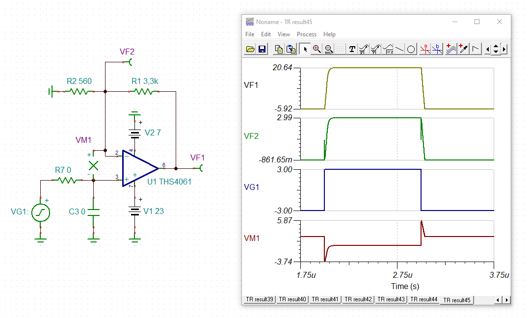
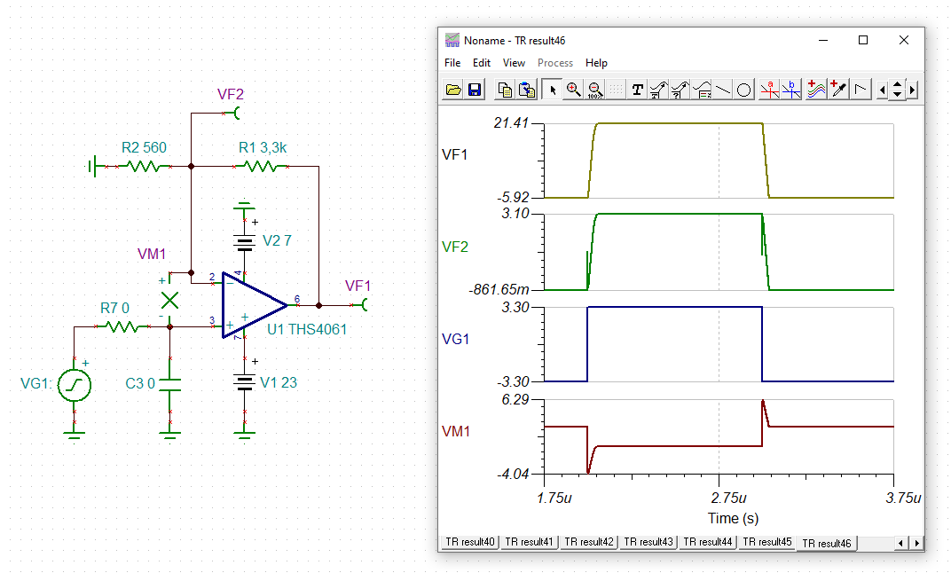
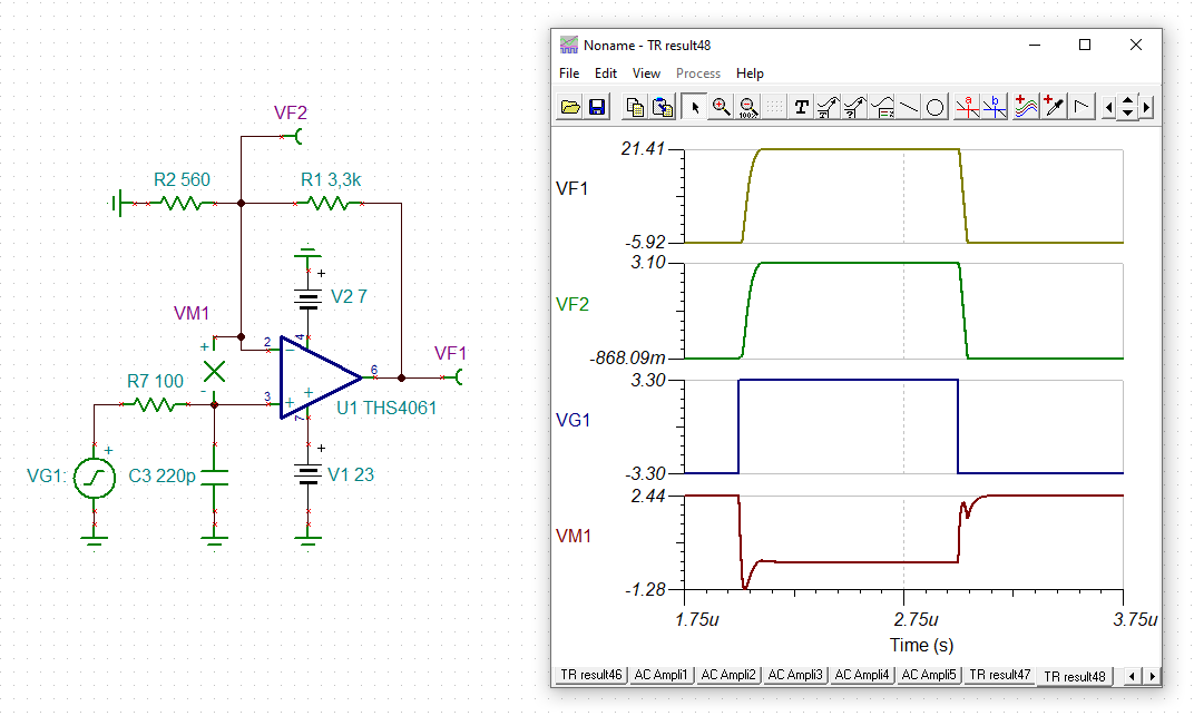
After an input override, the output signal of the THS4061 is seriously wrong for up to approx. 600ns.
This behaviour is not reproduced by TI-PSpice (see measurements).
Is there an extra setting for this in TI-PSpice?
Or is it not possible to see overriding/clipping effects with PSpice?
Thank you for your reply.
Regards, Karl
Hello Karl,
I am looking over your files now. When in the measured results section of your PDF, you refer to the four channels of the oscilloscope with names, such as Buffer-Out, OpAmp-Out, etc. Are these measured signals already probed correctly in the PSPICE file? Could you assist me in understanding which simulated signals I should be investigating?
From right now I can tell:
CH1: Buffer-Out -> (?)
CH2: OpAmp-Out -> Green signal, THS4061 output
CH3: OpAmp-In_P -> Red signal, signal generator into op-amp
CH4: OpAmp-In_M -> Not probed in simulation
I see you are overriding the input and expecting the SPICE simulation to convey a result in accordance with your real-world measurement. Could you explain how you have already attempted to set the input override in the PSPICE file?
The models are intended to be able to assist with simulating overdrive/override & clipping; since this is an older model I cannot ascertain what the intended limits on its use are for simulation. Please allow some time for me to look into the capabilities of the model, while you assist me in understanding the provided information.
Thank you for contacting the team on this matter; I will help you on this topic.
Best,
Alec
Hey Karl, I would not hold out much hope for accurate overdrive recovery simulation. At the designer transistor level, this requires an accurate number for the minority carrier lifetime in the staturated input stage base collector junctions. At the macromodel level, this is almost never a modeling item. The customer sim models are intended to accurately protray many (but not all) of the linear operating range performance over a wide range of external conditions - non-linear modes, like overdrive, and not usually modelled accurately - the sim will give something, but not necessarily related to the device operation.
Frohe Weihnachten Karl,
as Michael already mentioned the THS4061's Spice model is from 1999 and may only properly simulate the THS4061 during normal operation.
Take care, it seems that you violate the absolute maximum ratings of the differential input voltage (VM1 in the simulation). First, with an input signal amplitude of 3.0V:
You can see that the differential input voltage is +5.87V (VM1 = +5.87V) while the absolute maximum ratings only allow up to +4V. Also see the short glitch appearing at the -input of OPAmp (VF2).
And then, when you furtherly increase the input signal amplitude from 3.0V to 3.3V, the differential input voltage also exceeds the absolute maximum ratings of -4V (VM1 = -4.04V):
So, a small increase of input signal amplitude can make the THS4061 violate the absolute maximum ratings and can make THS4061 operate improperly.
It turns out that you dynamically overload the input of THS4061. A too fast edge at the input and a too slowly reacting THS4061 causes the develop of a dangerous differential input voltage glitch exceeding the absolute maximum ratings. A simple RC low pass filter at the input could do the trick. At least, you won't violate the absolute maximum ratings any longer:
One last word: HF-OPAmps are usually not designed to be driven into hard saturation, neither at the inputs nor at the output. It may need microseconds to fully recover from the overload condition. And if even a thermal derailment on the die is involved during the overload condition, for instance because of exceeding the absolute maximum differential input voltage, some weird effects for a duration of up to milliseconds may be seen.
If you plan to drive a HF-OPAmp into hard saturation, look for an amplifier which has the overload recovery time specified in the datasheet. And never violate any absolute maximum rating.
Kai
Hello,
thank you for the replies and Frohe Weihnachten to all.THS4061+2xBuffer_Sim+Measurements_20221223.pdf
In the *.pdf you can see the correlation of the measured signals with the simulation results. Basically, it was only about the behaviour of the OpAmp output after negative overload.
But I almost thought that the simulation for processes outside the specified opamp working range and the saturation effects mentioned by Michael would be difficult or not possible.
@ Kai:
thanks for pointing out the violation of the maximum ratings.
Do you know any HF opamps (min. 30V supply) for which the recovery times are specified in the data sheet?
Regards, Karl
unlikely there is such a part, if overdrive recovery is required, most folks use external Schottky clamping diodes like the BAV99
Hi Karl,
the THS4601 and the THS4631 discuss the "overdrive recovery" in their datasheets.
I would give the input low pass filter a try. And I would modify the input signal in order to prevent the output of OPAmp from clipping. Then you even may have success with the THS4061.
Kai
Hello Karl,
Thank for your updated reply. After reading through the conversation (now that I am back from holiday), it appears we have reached a point of discussing potential options & the limitations of HSAMPs modelling. I am bringing up our discussion in my weekly team meeting Thursday; I want to be certain of what capabilities and advice we may offer you for you application and needs.
@Kai & Michael; thank you for providing Karl with explanation and assistance. The forums are a bit more difficult to track over TI holidays.
Best,
Alec
Just to give you a little more background on this topic
Many years and companies ago I was doing all the original characterization and modeling on the 1st monolithic current feedback amplifier, the CLC400 - a part I had also designed so I had the full transistor models to work from as well. At 1st we thought it would be nice to report an overdrive recovery - however, as I drilled down deeper and deeper, the saturating junctions (that determine recovery time) moved around inside the circuit depending on the external gain setting and resistor values. Kind of threw up our hands at the point and just said - don't do it, use external clamp diodes and try not to saturate internal devices. I would not waste any time trying to improve the model on this issue.
Michael,
Thank you for this insight! I have had far less time and exposure to the intricacies of analog circuits, let alone current feedback amplifiers. I really appreciate the shared knowledge; it helps give context to everything I am working to learn & build expertise.
Best,
Alec
Oh and there is a very conspicous exception to spec overdrive recovery, that is the OPA698 and OPA699 output limiting amplifiers - everything was designed internally to recover very fast from ovedrive into settable output limits.