This thread has been locked.

If you have a related question, please click the "Ask a related question" button in the top right corner. The newly created question will be automatically linked to this question.

MPY634: MPY634 output magnitude according to SF.

Part Number: MPY634

Hello

i'm using the MPY634 mixer chip for making Lock in amplifier.

To configure MPY634's SF(Scale Factor) to 1, I configured the circuit as below.(MPY634 datasheet figure 1.)

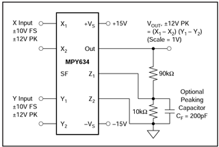
However, looking at the resulting values, it doesn't seem like the SF is 1.

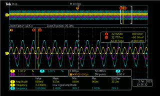
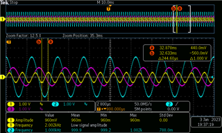
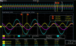
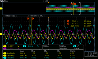
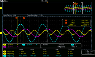
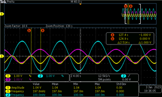
The image below is a waveform taken with an oscilloscope. The labels (2) and (3) of the oscilloscope are inputs with the same frequency but different magnitudes,

and Label (1) is the result of mixing the values ​​of (2) and (3).

 ((Input frequency : 1.6Khz)


 (Input frequency : 1Khz)

 (Input frequency : 100Hz)

 (Input frequency : 10Hz)

 (Input frequency : 1Hz)

 (Input frequency : 0.1Hz)

Contrary to expectations, The slightly smaller output value came out
Is it a circuit wiring problem or a short circuit problem inside the chip?
Thank you.
 
 
  • Hi Hoonmin,

    Based on the phase and frequency of the signals the MPY634 does appear to be multiplying as expected, however the magnitude of the output is about 1/2 of what I would expect for a scale factor of 1. Your resistor color codes appear to be correct but I would double check with an ohmmeter to make sure they are the expected value.

    What impedance are your signal generators and oscilloscope channels set to? Breadboards can have 10s of ohms of impedance in the tracks which could result in unexpected attenuation if your equipment is set to 50Ω impedance. Do you have any additional resistors or filters connected to the input or output pins that are not shown in the image?

    Additionally, if your input signal is coupling through the breadboard into the X2 and/or Y2 pins there may be an additional subtraction occurring that is not accounted for. I recommend connecting X2 and Y2 to ground and probing these pins while the input signal is active to ensure that X2 and Y2 are 0V.

    Regards,

    Zach

  • Hi Hoonmin,

    how are the pins X1, X2, Y1 and Y2 connected?

    Have you tried the circuit from figure 2 of datasaheet?

    Have you noticed the phase shifting between the input signals when decreasing the frequency?

    Kai