This thread has been locked.

If you have a related question, please click the "Ask a related question" button in the top right corner. The newly created question will be automatically linked to this question.

OPA656: Amplifier runs very hot

Part Number: OPA656

Hello.  

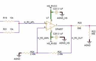
I have designed in the OPA656N amplifier and am quite pleased with the performance.  Except for the excessive heat generated by the part.  We are entering production and I am under a great deal of pressure to get this solved.  Package is SOT-23-5

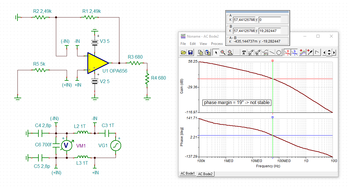
1) Amplifier is a unity gain summation amplifier, (see schematic).

2) Solid ground plane underneath the footprint, (see layout).

3) Power supplies are from LDO which are very clean.

4) All components are close to the associated pins, (see layout).

5) Measured current is approximately 15ma per power pin.  Total power is 150mw.

6) Output is stable with no oscillations. 

Measured temperature at top of component is 50 degrees Celsius with a room temperature of 21 degrees Celsius.   

I do not understand why this device is running so hot.

I have been designing with T.I. parts since 1978 and here's hoping your team can solve this one.

This is a great amplifier with low bias current, and low output offset.  The only issue is the heat.

We are getting ready for production and have to solve this ASAP.  

Attached are the clips of the schematic and layout.

I look forward to a quick response,

Thanks,

J. Allan Jarvo

Principal Hardware Developer

Email:     jarvo@kwesst.com

Cell:       613 293-3096

 KWESST Micro Systems Inc.

Canadian Head Office:

155 Terence Matthews Cr.

Ottawa, ON. K2M 2A8

www.kwesst.com   TSXV: KWE

This message and/or attachments may include information subject to KWESST Corporate Policies and is intended to be accessed only by authorized recipients. Use, storage and transmission are governed by KWESST and its policies. Contractual restrictions apply to third parties. Recipients should refer to the policies or contract to determine proper handling. Unauthorized review, use, disclosure or distribution is prohibited. If you are not an intended recipient, please contact the sender and destroy all copies of the original message.

  • Hello,

    Thank you for providing such a detailed summation of your design and its parameters.  I have the following bit of information to share with you:

    The OPA656 performing with a top temperature of 50°C is not abnormal nor a cause for alarm.  The limit of the device's junction temperature is 150°C; the next step is to calculate the junction temperature when the case/top is at 50°C.

    The Thermal Information located in the back-portion of the OPA656 datasheet is not as accurate or effective a way to calculate junction temperature (and therefore device compliance with recommended conditions & abs max conditions).  I recommend utilizing the equations and descriptions present in the document Semiconductor and IC Package Thermal Metrics.  While the entire document is resourceful, the calculation of interest today is in Section 3: Junction to Top of Package.  The ΨJT Junction-to-Top thermal characterization parameter is the recommended value for use in our needed calculation: the calculation of the junction temperature.  The equation discussed finds the junction temperature TJ = TC + (Power x ΨJT).  Your measured TC = 50°C; the ΨJT = 24.4°C/W; the Power = 150mW.  The resulting value is TJ = 53.66°C.

    As it can be seen, the result of 53.66°C is within a large amount of margin from 150°C.  I see no issue with the OPA656 operating at 50°C, even when idle.  I recommend showing the calculation, comparing the result to the absolute maximum value, and proceeding to close-out the issue in order to resume production.  It is a good thing to observe and calculate temperatures; in this case your investigation results in there being no problem, as I can understand it from what you shared.

    Please let me know if you require additional assistance.

    Best,

    Alec

  • The other way to look at this Mr. Jarvo is from your 21C ambient to 50C case that imputes a 260deg thermal impedance to the case with 150mW Pd. Does seem high, the SOT23-5 is not a very good thermal package. Circuit looks fine, probably too late to consider but there are many newer JFET input devices to consider that might be lower quiescent. Would need other design goals, SSBW, slew rate, noise, offset to screen down to an alternate. 

  • Hi Allan,

    hhm, for my taste the feedback resistances arround the OPA656 look very very high ohmic. This can cause stability issues in combination with the common mode input capacitance of OPA656 (erosion of phase margin by introducing unwanted phase lag). And look how low the phase margin is, only 19°:

    allan_opa656.TSC

    With 250R resistors recommended for a gain of 2V/V in the datasheet the phase margin looks way better:

    Not sure whether this will solve your heating issue, but I would decrease the feedback resistors. Decrease them from 2k5 to 1k in a first step (resulting in phase margin of 32°) and see what happens.

    Kai

  • And another way to test if this is a low phase margin issue, adding 1.5pF across the feedback R shapes the noise gain to give about 62deg phase margin, 

  • Yes, even better than reducing the feedback resistors as this would additionally increase the heat dissipation within the OPA656.

    Kai