This thread has been locked.

If you have a related question, please click the "Ask a related question" button in the top right corner. The newly created question will be automatically linked to this question.

INA286: INA286 output noise issue

Part Number: INA286
Other Parts Discussed in Thread: INA282, INA293

Hi, Support Team

1. The load is an electronic load with CC mode and we have also applied a CV on Shunt-Resistor to generate a DC current (all PWMs and Power Stage are stop), the output damping is the same.

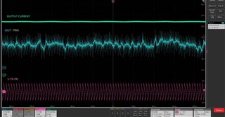
2. The pink signal is LLC - transformer primary voltage.

3. we have also adding a RC filter on the output, (180ohm+ 100pF~10nF) and Between PIN1 and PIN 8 add 22pf cap and CSL4 value increase to 220pf but cannot fixed noise issue...

Q1: if current shunt over 1.5A, output noise will be worse. Is about internal switch causes the output noise?

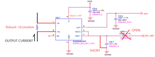
schematic as below chart:

measured as below chart:
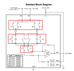
INA switch:

if any suggestion, Please advise me.

Thanks,

Best regards,

Lawrence

  • Hi Lawrence,

    as the peaks at the output of INA286 are synchronous to the peaks from the input signal, this doesn't seem to have to do with the "internal switches" of INA286.

    I think it has to do with the fact that your input signal heavily exceeds the bandwidth of INA286 which is 10kHz. Form the scope plot your input signal contains a 200kHz fundamental? Is it right? And think only of the far reaching harmonics of your input signal. So, you very probably totally dynamically overload the INA286.

    What is the scope showing when you increase the R of low pass filter from 180R to 1k?

    Kai

  • Hi Lawrence,

    I agree with Kai’s assessment.

    I suggested the following in the other duplicate post (which I’ll close and continue here) –

    You could run an experiment to see if it is due to input disturbance. You can apply a 2.5V reference voltage to IOUT_REF, shot  both IN- and IN+ pin to a constant voltage, 5V for example. The output signal should be stable.”

    Alternatively you could keep the REF grounded, and remove the shunt resistor and then apply a constant differential voltage to the INA286. Compare the output waveforms should tell us where the noises comes from.

    Regards, Guang

  • Hi, Kai and Guang

    Here is the current condition, but noise cannot fixed
    1. The reference already tied to ground.
    2. short both IN- and IN+ pin and disconnect to R_shunt.
    3. All PWMs and Power stage are stop

    We will try to higher bandwidth and unidirectional current sense (INA293A3 and INA293A4)

    If any suggestion, Please advise me.

    Thanks,

    Best regards,

    Lawrence

  • Hi Lawrence,

    the really interesting question is whether the "transformer primary voltage" is still connected to the inputs (pink signal).

    By the way, connecting the REF pins of INA286 to signal ground is no good idea, because with no input signal the output will leave the linear operationg range of INA286 and get slammed into saturation. What you observe at the output of INA286 then will not be a representative behaviour.

    Kai

  • Hi Lawrence,

    I agree with Kai. When inputs are shorted to ground (or a fixed common mode), I'd expect the INA282 output to be fairly quiet, except for its intrinsic noise, at a minimum we shouldn’t see the correlated peaks.

    But you’re welcome to experiment with INA293, which is newer and has much improved specs at a better cost. Please advise your findings when available.

    Regards, Guang