This thread has been locked.

If you have a related question, please click the "Ask a related question" button in the top right corner. The newly created question will be automatically linked to this question.

TLV8801: Create Rail splitter Capacitance Load

Part Number: TLV8801
Other Parts Discussed in Thread: TLE2426, , TLV6001, LMV321, TLV9062, TLV9051, TLV9052

Hi

I am trying to design rail splitter similar to TLE2426 since we are not able to use this part to package and availability limit.  I am doing something wrong on Calculating Riso, so I will be appreciated if you tell me what I am doing wrong.
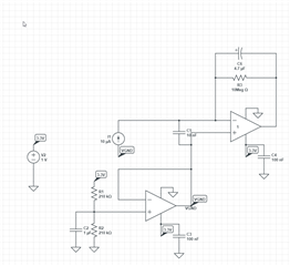
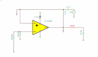
Original Circuit:

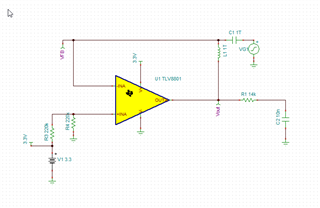
In order to make opamp to be stable with output capacitance I need to calculate Riso which make the system stable.

Base on ti training stability 5 I have to calculate Riso to set the zero at Fzero:

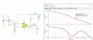
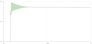
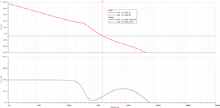
base on Tina simulation of this circuit:

I actually made mistake. 

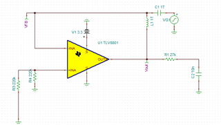
Fzero where Aol = 20db => Fzero= 590 =>  RISO = 1/2*pi*590*10n =~ 27k

...

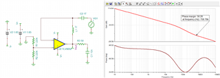
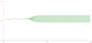
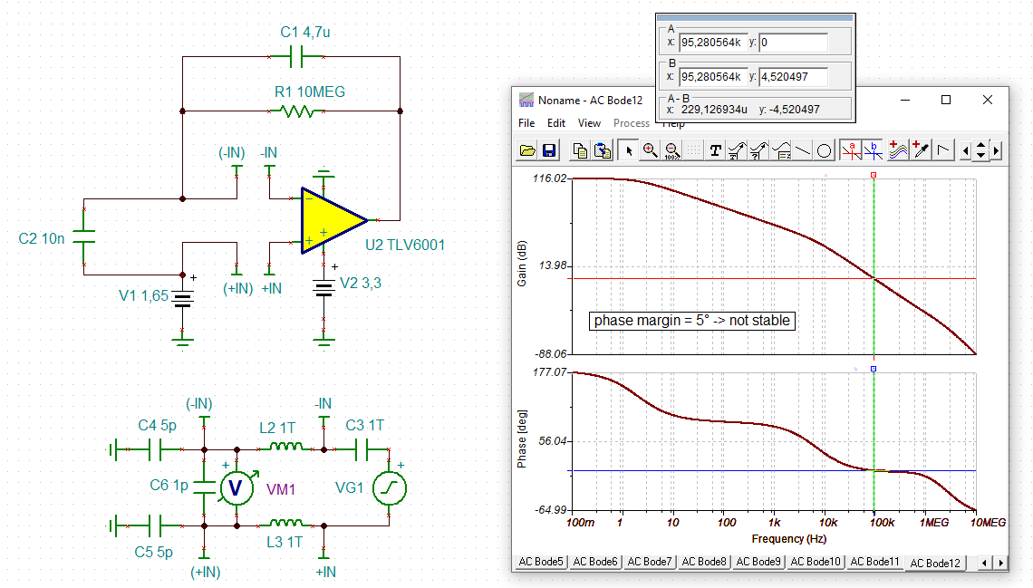
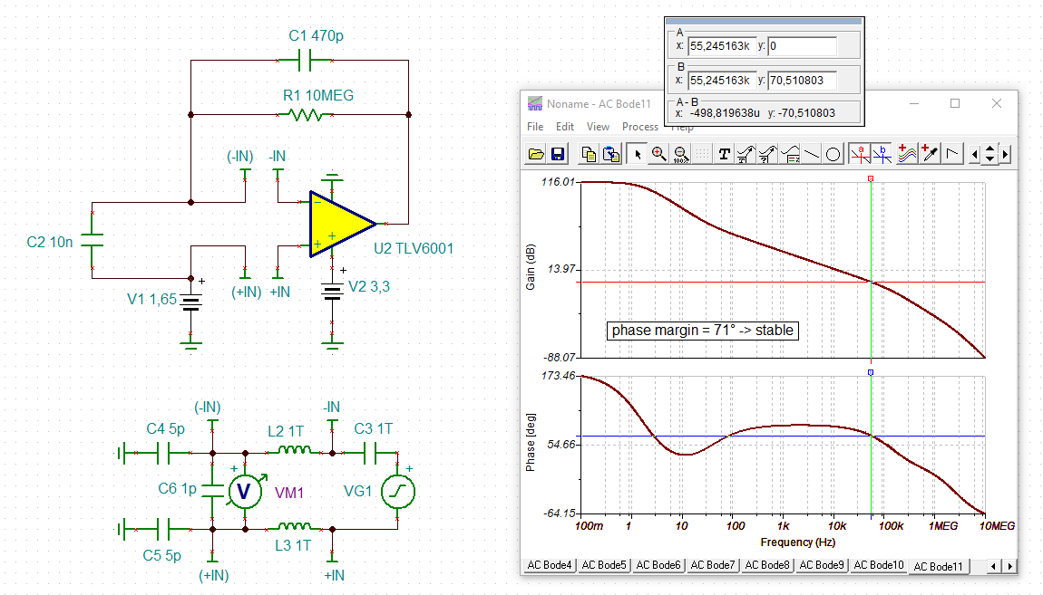
When I add 27k to system still opamp is not stable since at 0db the phase is under 45.

Please let me know if you have any questions.

Thanks

  • Hi Amir,

    I haven't confirmed your simulation so far. I only want to say something general: OPAmps drawing ultra little supply current like the nano-OPAmp TLV8801 are very critical with capacitive loading and may need isolation resistors in the 10k or even 100k range. Section 7.4.4 of datasheet supports what I'm saying and mentions an isolation resistor between 30k and 50k.

    So, it may be a good idea to choose an OPAmp which draws somewhat more supply current.

    Kai

  • Hi Kai,

    Thanks for the response. do you have any suggestions.  How about TLV6001 or  LMV321, that one is limited to 150pF. 
    I will go ahead and simulate using this opamp and let you know the results.

    I found this document from ti  which use TLV9062.

    Thanks again.

  • Hi Amir, 

    I looked for options that were similar to the TLV8801 and TLE2426 in terms of key specifications and ran stability analysis to check if the circuit with work for the application you're looking for. I listed two options below for the TLV6001 and the TLV9051. Key differences between the two devices can be seen through this link: Comparison table

    In summary, the TLV6001 is a low power option that can drive the 10n load with the right Riso value, but this Riso value will need to be higher (~200ohms) than if you used the TLV9051 due to the output current differences. The Riso will cause a voltage drop at the output but if this voltage drop is satisfactory for the application, you can use the TLV6001. Otherwise the TLV9051 is a good option with a large output current drive and minimal voltage drop across the Riso (~50ohms) to achieve a stable circuit. 

    TLV6001 simulation: (I used a split supply for both simulations in order for the output to not rail, but each part will work for the single supply application.)

    TLV9051 simulation: 

    Please let me know if you have any questions.
    Thank you!

    Best Regards,
    Ashley

  • Hi Amir,

    designing a rail splitter with OPAmps can be very tricky and becomes the more complicated the higher the capacitive loading is. It's true that you can stabilize the rail splitter by using a sufficiently high isolation resistance in front of the capacitive load. But all signal and ground currents will run across this isolation resistance and will shift the pseudo ground potential. At the end you get a very poor signal ground with lots of ground noise which superimposes to the signals and may totally ruin the performance of your circuit. The idea of using the TLE2426 just is to profit from the very low output impedance of TLE2426 which is no longer the case when you build the rail splitter with discretes and need a much much much higher isolation resistance.

    Happily, beside using a rail splitter there are many other ways to generate a pseudo ground in a single supply circuit. And these other ways may be able to handle the capacitive loading much better, in particular when they allow the use of a higher isolation resistance. So, you may want to generate the pseudo ground locally by the help of individual OPAmps or voltage dividers instead of generating the pseudo ground globally with a rail splitter for all involved circuits at the same time.

    Can you show a schematic of the circuit for which you want to design the rail splitter?

    Kai

  • Hi Kai,

    Thanks for the detail answer. Below is my schematic and as you can see, I have huge amount of capacitive load (5uF) which make system unstable.

    Below circuit is transimpedance amplifier with single source power supply.

    I have used TLE2426 and it works great but, in this design, I am limited on space. 

    I will be appreciated if you can tell me how you calculated the RISO for previous opamps. 

    Please let me know if you have any questions.

    Thanks

  • Hi Ashley,

    Thanks for detail answer, could you please let me know how you calculated 50ohm on TLV9052.  Also, I see on your simulation you are suing V- as negative supply instead of GND. 

    Thanks

  • Hi Amir, 

    I estimated the Riso value by changing it in the TINA simulation until I got a phase margin greater than 45 degrees. You can calculate Riso through the same method as calculated in the TI Precision Labs Stability video you referenced earlier if you are wanting a greater phase margin (60 - 90 degrees). 

    Fzero would equal 171.77kHz and then Riso is calculated to be 93.1ohms.'

    In my simulation, I used split supply because otherwise the op amp would be railed since IN+ is at ground. This would cause issues with the AC simulation. The alternative solution is to put a DC bias at the input pin. 

    Please let me know if you have further questions.
    Thank you!

    Best Regards,
    Ashley

  • Hi Ashely,

    Thanks for detail answer and I think this solve my problem for simulation, I will reply to this post if I have another question.

    Thanks

  • Hi Amir,

    I cannot see a 5µF load in your schematic.

    Do you want to build a TIA (transimpedance amplifier) to amplify the signal of a photodiode? Shall the feedback impedance of TIA be 10M in parallel with 4.7µF? And is the detector capacitance 10nF? And do you want to bias the +input of upper OPAmp and the anode of photodiode with 3.3V / 2 = 1.65V?

    Also, what OPAmp packages do you intend to use?

    Kai

  • HI Kia,

    Is not exact 5uF load the 10nF and 4.7uF across TIA cause huge spike as you can see in below schematic. Removing the 10nF  capacitor solve all the problem but I need that to prevent any unwanted spikes. 

    1. Yes, I want to bias the sensor to half of input voltage which is 1.5V.

    2. I can use SC70 or DFN package or smaller.

    I was able to little remove spike by changing circuit to below but not as good as I want.

    Attached is my simulation file. TIAtran.TSC

    Please let me know if you have any questions. 

    Thanks

  • Hi Amir,

    is the 10nF in your circuit the detector capacitance? If so, this detector capacitance itself may be responsible for the instability and not the pseudoground generation. In this case the TIA has to be stabilized first.

    Kai

  • Hi Kai,

    So, I understand 10nF is main cause of oscillation but what you can do on TIA to make stabilize.  Since this circuit is act as oscillator.

    I think I solved the problem by adding small resistor. to detector capacitor, however I have to check if this effect the linearity of system.

    Thanks

  • Hi Amir, 

    There is a TI reference design for a TIA circuit here: Photodiode amplifier circuit

    Best Regards,
    Ashley

  • Hi Amir,

    your circuit is instable because the 4.7µF feedback capacitance is too big. Because the OPAmp sees the 4.7µF in series with the 10nF detector capacitance, the output of OPAmp sees a too high capacitive load which ruins the phase margin, as the phase stability analysis shows:

    A ruined phase margin (<45° minimum) causes instability and can result in oscillation. And If the phase margin is only 5° as shown above, the circuit very probably tends to run into oscillation.

    One remedy is to decrease the feedback capacitance and make it way smaller than 10nF:

    amir_tlv6001.TSC

    10M and 470pF provides a corner frequency of low pass filtering of 34Hz. If this is not sufficient in your application add a passive low pass filter at the output of OPAmp. But do not increase the feedback capacitance.

    Kai

  • Hi Kai,

    I really appreciate your support I will try to review the files and let you know if I have another question. 

    Thanks