A related question is a question created from another question. When the related question is created, it will be automatically linked to the original question.
If you have a related question, please click the "Ask a related question" button in the top right corner. The newly created question will be automatically linked to this question.
Part Number: INA849 Other Parts Discussed in Thread: TMUX6219
Dear, TI support Team.
We would like to use INA849 to build a programmable gain circuit with a minimum 10up-p, maximum output amplitude 10Vp-p, bandwidth from 500Khz to 1MHz, and gain steps of 8. Are there any TI MUXes that are good for gain switching? We would like a reference design for the INA849+MUX.
It is possible to use multiplexers to switch the RG resistor on the instrumentation amplifier, however, the designer needs to be aware/careful with the effects of the analog switch RON resistance, and parasitic switch capacitance. Also, the designer needs to select multiplexers that accommodate the full analog signal range of the INA849.
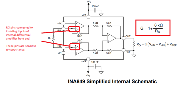
Multiplexers have an associated CIN/COUT parasitic capacitance. The RG pins of the INA849 instrumentation amplifier are sensitive to capacitance causing potential stability issues. This sensitivity is worst at the lower INA gains, for example, G=1V/V. The INA849 is a relatively high-bandwidth instrumentation amplifier and will be quite sensitive to switch capacitance at lower gains.
The gain of the INA849 is set with the total RG resistance; where the INA849 gain is given by:
Gain = 1 + 6kΩ / RG
All IC analog switches have an associated RON resistance, this switch RON resistance varies non-linearly with switch voltage and temperature. This RON resistance will be in series with the RG resistance, and produce gain errors. The required ideal RG resistor value is lower at the higher gains, hence, the gain error sensitivity due to the RON series resistance will be high at the higher gains.
EDIT:: Increased gain on example to ensure stability 2-22-23
Below is an example, offering gains of ~50.5-V/V, ~100-V/V are required but the application allows a loose gain error specification:
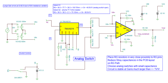
A low resistance (RON=~2.1Ω typical) is selected, covering the ±18V supply range such as TMUX6219 (or similar).
RG resistance is 28.2+30.1+RON= ~60.4Ω for Gain =~100 V/V and 89.1+30.1+RON = 121.3Ω for Gain=~50.5V/V.
The INA849 circuit is stable at G=~50.5V/V and G=~100V/V with this switch parasitic capacitance; however, it can be quite sensitive to the parasitic switch capacitance at lower gains
The gain error at G=50.5x is roughly, GE= (RON variation) / RG*100% =~2%; at G=100x is roughly GE=3.5%. Keep in mind, gain error will be higher for higher gain implementations.
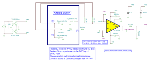
Splitting the RG resistor provides some level of isolation at the RG pin from the Mux capacitance, helping with stability.
As you can see, the INA849 requires low RG resistor values at higher gains, and the circuit becomes sensitive to RON resistance at high gains, making the use of an analog switch or multiplexers impractical at higher gains, unless the application has a loose tolerance for gain error and gain linearity error. Reed mechanical relays offer lower RON switch series resistance and better series on-resistance linearity, but the relays tend to occupy higher PCB area and tend to be higher cost than analog switches/multiplexers.
At lower gains, specially G=1 the INA849 will be quite sensitive to switch capacitance, making the circuit unstable.
You have mentioned you require 500kHz to 1MHz and gain steps of 8. What gains are required? What is the gain error tolerance?
The issue is that the impact of input capacitances (switch capacitances) on the phase margin of internal OPAmps cannot be compensated by suited phase lead capacitances, just because there's no way to externally connect them to the outputs of first internal OPAmp stage. This is furtherly complicated by the fact that the INA849 is very fast (22MHz and 35V/µs).
So, a multiplexer with switch capacitances in the pF range (neither 10pF nor 100pF ranges !) should be used. And at the same time the stray capacitances of the layout of the multiplexer circuit has to be minimized as well.
Another point which speaks against any multiplexer wiring at the RG inputs is that these termnals are extremely sensitive to charge injection by EMI and vulnerable against destabilizing feedback caused by stray capaciances. Because of that, it's best to leave the RG inputs completely untouched and to connect only one single resistor with the shortest connections possible. A gain setting could be performed by setting different attenuation factors at the +/- inputs of INA849 and by running the INA849 with the maximum gain. If this is not possible, I would better perform the gain switchings completely outside of the INA849.
In any case, the number of different gain settings at the RG inputs of INA849 should be reduced to the absolute minimum. This would help to limit the total switch capacitances and stray capacitances of layout.
As discussed on both posts above, reducing the capacitance on the RG pins is absolutely necessary. As Kai has explained, minimizing stray capacitance in the PCB layout, switch capacitance and the number of components is necessary. Choose the smallest capacitance analog switches available.
However, even the lowest capacitance switches available that will cover the ±12V range will often present capacitances in the 10's of picofarad range.
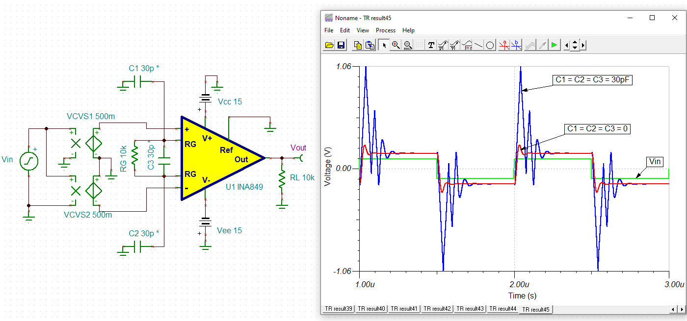
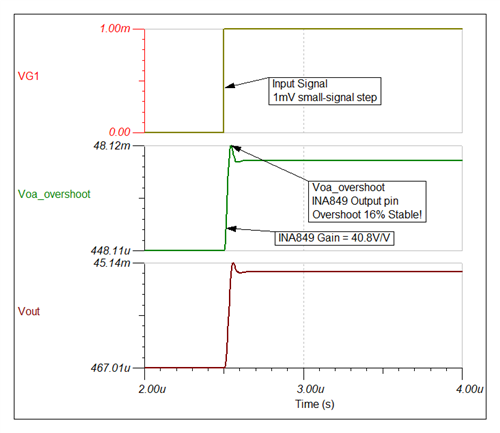
One trick that can help with stability when using INA849 at gains much higher than G>>1, is splitting the RG gain resistor into two resistors, and placing the analog switch in the middle. In the example below, the RG1, RG2, RG3 resistors is placed immediately in close proximity to the RG pins. This series resistance provides some level of isolation to the switch parasitic capacitance, and can help improve stability. The circuit below with a TMUX6219 is stable at G=~81V/V, G=40.81V/V tolerating a few 10's of picofarad at the higher gains.
There is small gain error at G=40.8V/V, since the switch is open and RON is not adding to the RG resistance; however, G=80.9V/V presents a large gain error at roughly ~3%. This circuit was only acceptable for a Customer that required low noise, high bandwidth, but had a loose tolerance for gain error in their mid-precision application. It is important to highlight that the circuit will be unstable at lower gains when using the INA849.
Because of the sensitivities to switch capacitance and RON resistance, and noise sensitivity to the RG pins, there are many limitations to the RG analog switch/mux approach, specially when using a high bandwidth INA849, which is quite sensitive to capacitance on the RG pins and requires small RG resistors to set gain.
yes, isolating the switch capacitances from the RG inputs of INA849 by the help of resistors is a very good idea
The same technique is used in TIAs where the switch(es) in the feedback loop are mounted closer to the output of OPAmp rather than directly to the -input of OPAmp and the gain setting resistors mounted to the -input of OPAmp are used as isolation resistors.
Thank you for your Great Advice. Thank you also for the simulation in TINA TI with your MUX and INA829 circuits. I understand to note the parasitic capacitance on the RG-pin of the INA849. However, the TMUX6219 has a Ron of 2ohm but a Con of 150pF. Our end products are circuit board leak testers. There are wires with large resistance to wires with small resistance, and we plan to use 8 steps because we want a wide range. Considering the gain bandwidth and slew rate of the INA849, I would like the A/D in the subsequent stage to have a range of 3V. We will decide the specifications with the end customer in the future. We also consider the gain-switching MUX.
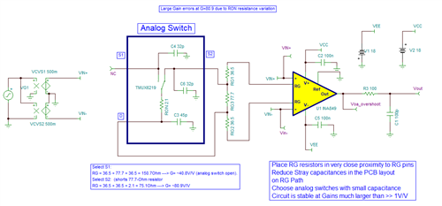
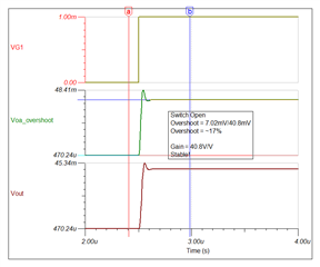
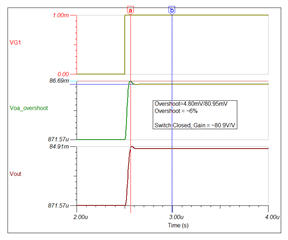
The TMUX6219 has CS(OFF) 33pF and CD(OFF) of 48pF. When the switch is open, on the circuit above, G=~40.8V/V, and circuit is stable with ~17% over shoot. When closing the switch the on Capacitance Cs(ON), CD(ON) is 148pF. This means the 148pF is distributed at the input and output pins of the switch or approximately ~74pF at the input, and 74pF at the output. The INA849 is at Gain=80.79V/V.
The circuit above is still stable at Gain =80.79V/V when TMUX is closed at this particular gain. On the simulation on the previous post, I used a simplified model to explain the concept of RON and parasitic switch capacitance. However, you could use the TMUX6219 SPICE model that updates the parasitic capacitance with the switch closed or open position to check stability. See below updated simulation using the TMUX6219 model.
As we have discussed, the worst case stability occurs at the lower gains. I would recommend to verify the overshoot is always less than 25% on all your gain settings to ensure conservative phase margin on your circuit.
Also, ensure to add the estimated parasitic PCB capacitances on your simulation. In the cPCB design, attempt to minimize the stray capacitance in the board layout, ensure to reduce switch capacitance as much as possible when selecting switches, and reduce the number of components connected to the RG pins since these pins are sensitive. The INA849 can become unstable, and it is the most sensitive at the lower gain settings.