This thread has been locked.

If you have a related question, please click the "Ask a related question" button in the top right corner. The newly created question will be automatically linked to this question.

OPA855: TINA-SPICE simulation gives unrealistic results

Part Number: OPA855
Other Parts Discussed in Thread: TINA-TI

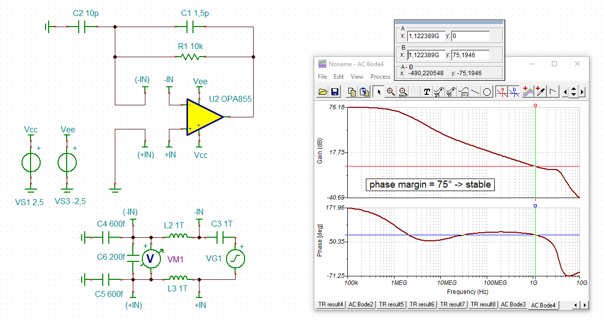
We are designing a photodiode detector circuit operating up to 3 GHz with the OPA855. Based on the photodiode capacitance of 4.5 pF and the gain curves in the datasheet, we should be using about 10k Ohms feedback resistor and we would expect about 40 dB of gain at these frequencies.

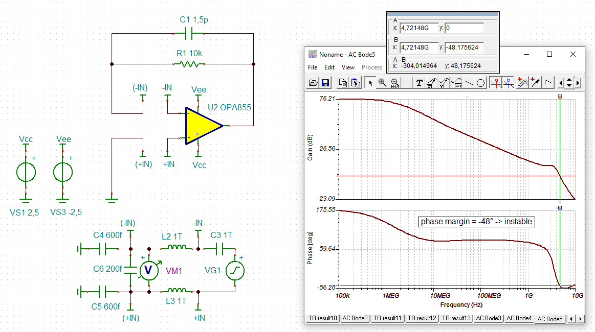
The problem we are having is that the output voltage appears to give 90-100 dB transimpedance gain, which is much higher than anticipated. Initially we did not trust the result and we started modifying the feedback and other components to see if we could change the output, but we always have very similar values at the output.

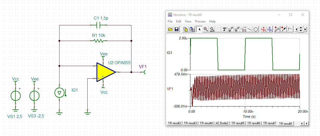
The circuit we initially try to use is shown below.

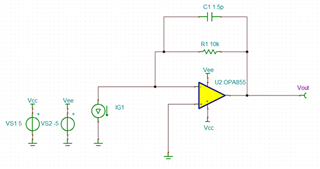
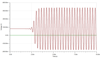
The resulting voltage output is about 350 mV amplitude with about 120 mV DC offset.

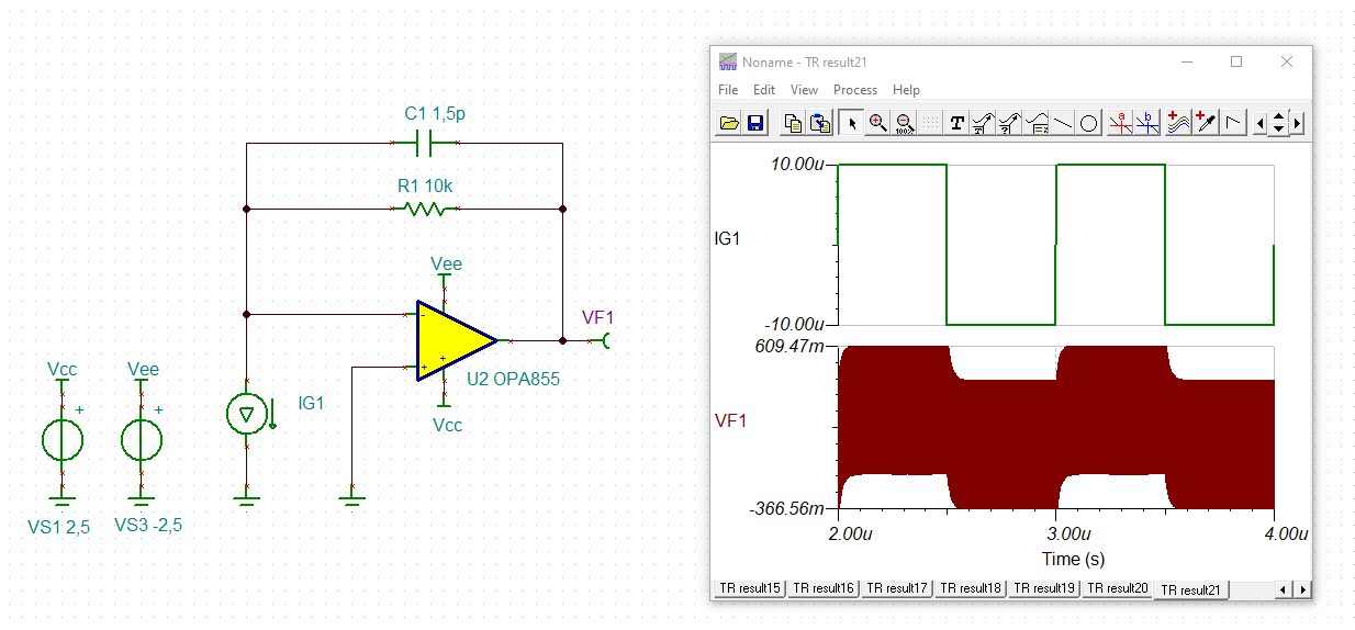
After adding the photodiode capacitance of 4.5 pF across the current source, we get about the same results.

Are the results we are getting accurate or realistic? Or is the TIA output oscillating.

  • would need your exact load to answer

  • Hello,

    Could you share the simulation results you are observing?  Or you could send over your TINA-TI file. 

    Best,

    Alec

  • The output voltage looks like the image below. We have tried variations on this with different feedback resistors and terminations, all produce some version of this with approximately the same amplitude. This is what made us this there is some oscillation happening.

  • Hi,

    the phase stability analysis shows that your circuit is instable:

    user_opa855_3.TSC

    Keep in mind that the OPA855 is a decompensated OPAmp which needs a minimum gain of 7V/V. But in your circuit the gain is only 1V/V.

    Kai

  • So how dow the circuit need to change in order to reach stability? Based on the phase graph it looks like we could run at 1 GHz, is that correct?

  • Hi,

    So how dow the circuit need to change in order to reach stability?

    The best remedy would be to use an unity-gain stable OPAmp. But if you urgently need to work with the OPA855, you can try to increase the noise gain at high frequencies. A 7.5...10pF cap from the -input of OPAmp to signal ground would do the trick. The same method is used to make the OPA855 run stably in a TIA when a detector capacitance is added.

    Based on the phase graph it looks like we could run at 1 GHz, is that correct?

    It's the purpose of the phase stability analysis to find out the phase behaviour at that frequency where the overall gain is 1V/V, in order to find out whether the condition of oscillation is fullfiled (gain = 1V/V and overall phase = 0°). And if at this frequency the phase margin is too small (or by other words, if the condition of oscillation is fullfilled), then you cannot use the circuit at any frequency, because the instability will always force to OPAmp to oscillate, independently of the frequency of the wished signal. Even the least amount of wideband noise which you always have in a circuit is enough stimulation to initiate and sustain oscillation.

    By the way, you have chosen a 10k feedback resistor in parallel with a 1.5pF capacitance. This forms a low pass filter of about 11MHz. Because of this you couldn't use a signal frequency of 1GHz anyway.

    Kai

  • The gain cannot be 1V/V if I am running at 3 GHz, it looks like it would be about 15-20 dB from your graph. Even at 1 GHz in the above circuit, you would have positive gain and positive phase. Isn't this exactly what one would want?

    I guess to summarize, the changes requried are:

    1) Remove the 1.5 pF capacitor

    2) Increase the feedback resistor to higher value

    3) Add capacitor from (-) input to GND

    Anything else?

  • Hi,

    The gain cannot be 1V/V if I am running at 3 GHz, it looks like it would be about 15-20 dB from your graph. Even at 1 GHz in the above circuit, you would have positive gain and positive phase. Isn't this exactly what one would want?

    This is a phase stability analysis and no frequency response simulation.

    And your circuit is still instable and oscillates:

    user_opa855_4.TSC

    This circuit would be stable:

    I guess to summarize, the changes requried are:

    1) Remove the 1.5 pF capacitor

    2) Increase the feedback resistor to higher value

    3) Add capacitor from (-) input to GND

    Anything else?

    Take my simulation files and check it out by yourself Relaxed

    Kai

  • Hello,

    In addition to supporting Kai's request to tinker & discover the stability circuit which fits your needs, please see the Stability section of these TI Precision Labs training videos: https://www.ti.com/video/series/ti-precision-labs-op-amps.html

    These videos use methods which may differ slightly from an optimal or custom method you can build for yourself, but they do offer some explanation and context which you may find useful.

    If you have questions about a circuit revision you create or understanding stability, please reconnect with us on the forum.

    Best,

    Alec