This thread has been locked.

If you have a related question, please click the "Ask a related question" button in the top right corner. The newly created question will be automatically linked to this question.

XTR116: PWM control for 4-20mA current loop with Microcontroller

Part Number: XTR116
Other Parts Discussed in Thread: ISO7310-Q1
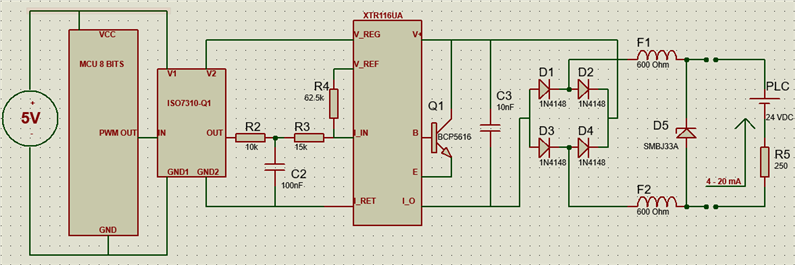
Hello,


We are trying to develop a 4 – 20mA current transmitter. The control is done by a PWM signal issued by a microcontroller.

I can't quite understand the values of R3 (Rin) and R4 (Ros). I need to know the considerations that I must have to find the values of R3 and R4 in the circuit. The current values are referential from notes found on the internet, but I'm not sure if they are correct.

I appreciate your help.

  • Hi Ivan,

    I need to know the considerations that I must have to find the values of R3 and R4 in the circuit.

    XTR116 is 2-wire V-to-I converter with 4-20mA current loop transmitter when input voltage, Viso is ranged from 0-5V. 

    1. Viso is the average voltage of the PWM input signal from PWM_OUT of the CMU's GPIO pin. The higher the PWM frequency, the better the accuracy of the PWM to Viso voltage signal (0-5Vdc is proportional to 0-100% PWM duty cycles, and LPF is used to obtain the average DC voltage from the PWM signals, which is in 50% duty cycles).

    2. IRET node is the floating node for XTR116 and ISO7310-Q1 isolator. The XTR116's GND signal is located at Vloop or 24Vdc supply as simulated. 

    3. V_REF or R4 should be measured at 4.096V wrt IRET pin, where Riso = V_REF/40uA = 4.096V/40uA = 102.400kΩ (this needs to a precision resistor, 0.1% or better, prefer 0.01%). 

    4. Rset or R3 should be configured as Viso/160uA =5Vdc/160uA = 31.25kΩ (this needs to a precision resistor, 0.1% or better, prefer 0.01%). 

    5. I_in = Io + Iiso = 40uA +160uA = 200uA, where the current gain of the XTR116 is 100 A/A (1 + R3/R4 = 1 + 2.475kΩ/25 = 100)

    6. When Viso = 0Vdc, Iout = 100A/A * Io = 100*40uA = 4mA (when there is no input signal or Viso = 0Vdc)

    7. When Viso=5Vdc, Iout = 100A/A(40uA + 160uA) = 20mA (when Viso = 5Vdc)

    8. The Iout responses from 4mA to 20mA are linear to the input voltage of 0Vdc <= Viso <=5Vdc 

    XTR116 03162023.TSC

    Enclosed is the reference information and videos about the 4-20mA current loop transmitter application, and we have many in the subjects. 

    https://e2e.ti.com/support/amplifiers-group/amplifiers/f/amplifiers-forum/1021937/faq-how-to-select-amplifiers-for-4-20ma-field-transmitter-applications

    If you have additional questions, please let me know. 

    Best,

    Raymond

  • Raymond,

    Thank you very much for your quick response and detailed explanation, I will design the PCB and we will carry out the corresponding tests.

    Greetings.