This thread has been locked.

If you have a related question, please click the "Ask a related question" button in the top right corner. The newly created question will be automatically linked to this question.

LM324: LM324: Indirectly driving capacitive load with DC accuracy

Part Number: LM324
Other Parts Discussed in Thread: TINA-TI

Hi all,

I'm referring to following thread:

LINK ORIGINAL THREAD

about LM324 stability and in particular to the last post where a numerical simulation was done by means of TINA-TI.
I've did same simulation using same source circuit file here below my result:
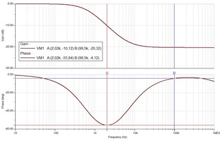
into the post was written "With the given components this results in a phase margin of 34° at 2kHz and 86° at 100kHz", how to see it into the above diagram?

Thanks

  • Hello Fabio,

    From the circuit in the thread, you will need to add the LM324 SPICE model into the circuit. This can be found on the product page here.

    From there, you will need to follow the steps from how to break the loop for a dual feedback circuit Dual FB Beta_plus and Beta_minus RevD(1).pptx

    Then you can right click the open loop gain (Aol) trace and select "Phase Margin..." and click on your graph. It will label your Aol trace with the amount of phase margin your circuit has.

    Best,
    Jerry 

  • Thanks Jerry,

    so from the simplified analisys show into the original thread and then by looking only at the resulting Bode Plot (show into my first post), is not possible to desume directly that:

    "With the given components this results in a phase margin of 34° at 2kHz and 86° at 100kHz"

    right?

    Thanks!

  • Hey Fabio,

    I believe Kai made an estimate of the open loop output impedance of the op amp and made a rough model of it being a 2k resistor. The change in phase from the components surrounding the device was then added to what your base phase change is with negative feedback (-90 degrees).

    Your worst case would be if your GBW achieves unity gain when the surrounding components have the most phase change This happens at 2kHz, which would be -55.84 of phase shift. Subtracting that from your original 90 gives you 145.84 total degrees of phase shift. 180 degrees of phase shift will get you to positive feedback and make your circuit unstable, so you have ~34 degrees of phase until you are back to 180 degrees of phase shift.

    Without knowing where the device GBW crosses unity gain, you are only really able to get a rough estimate.

    For the TI devices, we have our open loop output impedance modeled and the open loop gain modeled, to take out the guesswork for your stability simulations.

    Best,
    Jerry

  • Thank you, Jerry Relaxed

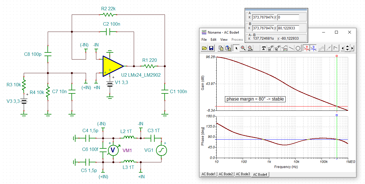
    Yes, what I wanted to do was to find out the phase shift introduced by only the feedback loop. So, what came out was a highly simplified phase stability analysis wihtout considering the additional effect of OPAmp. I remember that I had trouble to run the old Spice model of LM324. So, I neglected its impact on the phase shift. Also, at that time I wasn't knowing how to use the term "phase margin" correctly. Today I know that only the phase shift at unity gain is called "phase margin" and not the phase shift at any other frequency, because only the phase shift at unity gain can destabilize the circuit.

    Today, with the new Spice model of LM324 (from 2018) I would carry out the phase stability analysis this way:

    fabio_lm324.TSC

    This thread may also interest you:

    https://e2e.ti.com/support/tools/simulation-hardware-system-design-tools-group/sim-hw-system-design/f/simulation-hardware-system-design-tools-forum/1087610/tida-00489-pir-amplifier-stability-analysis

    Kai

  • Thanks Kai,

    this was the point, also thanks for the simulation file!

    Best regards!