This thread has been locked.

If you have a related question, please click the "Ask a related question" button in the top right corner. The newly created question will be automatically linked to this question.

LMH6401EVM: My eval board is not giving any gain for single Dc supply

Part Number: LMH6401EVM

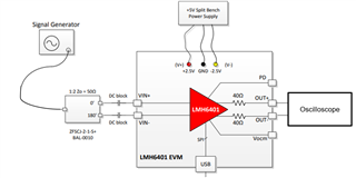
Hi, I am working on a Eval board LHM6401 Variable gain amplifier. In the datasheet it is mentioned that the eval board works on both single as well as dual supply, but I am not able to obtain any gain when trying for single input supply. Can you help me out troubleshooting this?

Please note that, I have connected ground to V-.I have used proper baluns to ensure differential RF input. I am not using VCOM so I have left it open and I have provided a proper DC input of 5V.

  • Hi Sanskar,

    Thank you for your question. I have just a few follow on questions to better understand your situation prior to making recommendations. 

    1. What voltage value are you using for the V+ pin? 
    2. What input signal are you supplying via the balun?
      1. Are you also applying the 5V as a DC bias to the input? 
    3. How are you measuring the output? Is the test equipment referenced to ground?

    Additionally, when using a single-supply, the VOCM pin will be biased by default to mid-supply if no external supply is given (i.e. if V+ = 5V, VCOM = 2.5V). 

    Thank you,
    Rachel 

  • 1. I am using 5V for the V+ Pin.

    2.I am providing a RF input signal of 400 MHz to the balun through a signal generator.

          a. No, I am not applying any 5V DC bias to input

    3.I am measuring the output on a spectrum analyser which is referenced to ground, which works perfectly fine.

    I want you to note that, 

    1. I am able to obtain all the proper results for dual-supply for the same Eval board.

    2. I have also tried both cases in which,

          a. Once I left the VOCM as it is, without any external supply to it.

          b. Then I tried providing 1.2V to VOCM after removing (RCM+,RCM-) voltage divider network from the board.

  • Hello Sanskar,

    Thank you for the additional clarification on the 5V supply. I have listed a few additional questions / areas to trouble-shoot below:

    1. Are you using a Balun on the output of the device before measuring the signal?
    2. Is the supply current at the same value?
    3. Is the power-down pin disabled?  

    Thank you,
    Rachel 

  • Hi Rachel,

    1. Yes, I am using a balun on the output of the device before measuring signal.

    2. Yes, the supply current is at the same value but I am getting a slightly high supply current of 90mA.

    3. Yes, the power down pin is disabled.

    Thank you,

    Sanskar

  • Hello Sanskar,

      We apologize for delay in response; we had a holiday on Friday. One question on my end, what is your input voltage (Vpp or V peak to peak) range at the input (amplitude and DC bias) for the 400MHz input signal?

    Thank you,
    Sima 

  • Hi Sima,

    My input voltage is 5V Vpp( when on single supply).

  • Hi Sanskar,

    Appreciate your patience during the holiday. I have ordered an EVM to try and replicate the issue you are having on our bench. I will follow up with additional details as soon as I am able to.

    In the meantime, I have a few follow up questions:

    1. What type of balun are you using? 
      1. Some RF Baluns (such as BAL-0010) would typically be grounded on one side, which would force both input nodes to 0V DC and cause an input common mode violation when operating with a single-supply. However with that same configuration operating on a split-supply, there would not be a violation. 
    2. Are you supplying a mid-supply voltage to the BIAS test point on the EVM and have populated a 0Ω at R10 and R11? 

    Thank you,
    Rachel

  • Hi Rachel,

    1. The part number for the RF balun I am using is ADT2-1T+.

    2. no, I am not providing any voltage to BIAS test pin and have not populated R10 and R11.

    Can you also suggest a balun part number suitable for this case?

  • Hi Sanskar,

    Thank you for those details. The balun you are currently using does have DC isolation, which means an additional DC blocking on the input should not be necessary.

    Upon further discussion with the design team, we have identified a few additional points of potential cause for concern.

    1. Can you add a DC block to the output of the device and then connect it directly to the scope?
      1. Based on the amplifiers supply current of 90mA, it is possible that with the connection of your scope referenced to ground, that a DC current is being drawn through the output and is causing an overload condition. 
    2. What voltage are you seeing on the input and output of the device when attempting to run it on single-supply with the 5V Vpp input signal?
      1. Are you seeing an input common mode voltage (probing at input pins of the amplifier) of approximately 2.5V when you supply that input? 
    3. If you were to input a much smaller signal, such as a 1V or 0.5V Vpp signal, what do you see on the output?
      1. There is concern that the maximum input differential voltage conditions may be violated on a single supply with that large of an amplitude. 

    Any scope screenshots you could share of these cases would also be very helpful.

    Thank you,
    Rachel 

  • Hi Rachel,

    1. I am already using the same balun ADT2-1T+ on the output as well, so I guess that acts as a DC block.

    2. I am seeing a voltage of 5V only on the input of device.

    3. When applying a smaller signal, I see nothing at the output.

    Please note that, in next few trials I tried

    1. providing a 2.5 V mid-supply to BIAS pin on EVM after populating 10k R10 and R11. I did not receive any signal. After, that I tried reducing the BIAS voltage to 1.4 V, I still could not see any signal.

    2. providing 1.4V to VOCM pin after removing the voltage divider network( Rcm+, Rcm-), I was still not able to receive any signal.

  • Hi Sanskar,

    Thank you for sharing those additional details and for trying our recommendations. At this time I do not have any additional questions. As a next step, I would like to try and replicate this issue within our lab.

    I am waiting for the EVM board to arrive to our facilities for me to test. I will reply here with any findings or additional suggestions at that time.

    Thank you,
    Rachel 

  • Hi Sanskar,

    Thank you for your patience. I received the board and was able to complete some testing in our lab. I did not make any hardware changes to the board, and ensured that the jumper pin connected to PD was left open. 

    I connected the EVM to a split supply of 5V (-2.5V on V- and 2.5V on V+) with a 1MHz, 5Vpp (0V offset) input signal. I then connected the outputs differentially into the oscilloscope and observed the expected result of a 2.5Vpp signal based on the default setting of -6dB of the THS6401. I received a supply current of 70mA during this test, which is close to the 69mA expected value. Below is a diagram of this set up.

    I repeated the testing with an additional balun & DC blocking configuration on the output, connected the single-ended output to the oscilloscope and saw the expected result. 

    I then connected the EVM to a single supply of 5V (5V on V+, V- = GND) also with a 1MHz, 5Vpp (0V offset) input signal. I then connected the outputs differentially into the oscilloscope (without the additional balun). I observed the same expected result as above (2.5Vpp signal), including a supply current of 70mA. I repeated this exercise with a balun and DC block on the output, connecting to the oscilloscope with a single-ended signal, and observed the same result. 

    Thank you,
    Rachel