This thread has been locked.

If you have a related question, please click the "Ask a related question" button in the top right corner. The newly created question will be automatically linked to this question.

INA237-Q1: Getting a connection error with the sensor

Part Number: INA237-Q1
Other Parts Discussed in Thread: SYSCONFIG

Hi Experts,

Our customer needs assistance, he has bought recently an ina237-q1 sensor smd variant and programmed it by hisself to work with an esp32 microcontroller. It works fine.

Now his question is how the triggered measurement works and how the continuous measurement works as well since he is getting a connection error with the sensor after 100 times reading from all registers of the sensor.

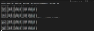
this is the error he get after 1 min running the sensor

during the 1 min period the sensor works just fine.

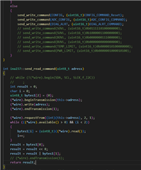
this is how he programmed his esp32 to connect to the ina237-q1 sensor.

We hope to receive your advice. Thank you.

Best regards,
Gerald

  • Hello Gerald,

    I recommend having the customer compare his code to the code in SysConfig: https://dev.ti.com/sysconfig/index.html?product=ascstudio&module=/ti/sensors/currentsensor/INA237. Which helps generate C-code based on desired configuration settings. There are also convenient read/write functions for communicating with the device. 

    It looks like they may be using the Arduino IDE, so here is a forum post that shows how to convert the SysConfig code to an Arduino project: https://e2e.ti.com/support/amplifiers-group/amplifiers/f/amplifiers-forum/1207381/ina239-vcp-monitor-4-click-using-the-ic--/4556160#4556160

    Regards,

    Mitch

  • Hi Mitch,

    Thank you for your response. I will comment again if we need further assistance.

    Best regards,
    Gerald

  • Hi Mitch,

    The customer do still want to know how to use the ina237-q1 sensor in the triggered measurement mode.

    What should he send to the ina237-q1 sensor when he wants it to measure the current and send it back?

    Should he write the current register to trigger a single shot measurement, or the config register, or which register?

    And in continuous mode should he use the alert pin for the conversion ready flag, or is it ok to request the current from the sensor, when it is still measuring?

    If not, how should he know when he can send read command to the current register?

    Kind regards,
    Gerald

  • Hey Gerald,

    A triggered conversion is started by writing anything to the ADC_CONFIG register. Conversions will then be started based on the value in the MODE bits of that register. You can use the conversion ready bit or enable conversion ready on the alert pin to know when the triggered conversion is ready. (or you can just wait a sufficient amount of time, as the data will remain in the register until after the next conversion is complete). 

    In continuous mode, the data can be read at any time, including during a conversion. The result register will hold the most recently converted value. The conversion ready flag/alert can be used to monitor when a conversion is completed if desired, but it is not necessary. 

    Regards,

    Mitch