Because of the holidays, TI E2E™ design support forum responses will be delayed from Dec. 25 through Jan. 2. Thank you for your patience.

This thread has been locked.

If you have a related question, please click the "Ask a related question" button in the top right corner. The newly created question will be automatically linked to this question.

LMC6081: input resistance

Expert 5750 points
Part Number: LMC6081

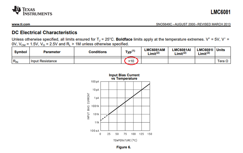
Input resistance is stated as >10Tohm in datasheet.

The assumption is that the reistance from input to GND is the same as the input resistance? 

But that is not the case.

Do you have a value for the reistance from e.g. negative input to GND?

Regards

Andreas

  • Andreas,

    The input common-mode resistance, Rin_cm, is the change of the input bias current (IB) with the change in the input common-mode voltage (Vcm):  

    Rin_cm = ΔVcm/ΔIB

    Unfortunately, we do not have the IB vs Vcm graph in the datasheet to confirm 10Tohm spec but it implies a change of 1pA with 10V change in Vcm at 25C, which would be difficult to measure.  Could you show the schematic and setup for your test? 

    Having said that, keep in mind that since IB in LMC6081 roughly double every 10 deg C (see above), this implies that everything else equal the Rin_cm at 125deg C would be (2^10) = 1024 times lower (~10Gohm) than what it is specified at 25 deg C (~10Tohm).

  • hi Marek,

    when desoldered customer is seeing 550kOhm between input and ground. Can you share your thoughts about that?

    Regards

    Andreas

  • Hi Andreas,

    desoldering can damage the OPAmp by overheating. This may be one cause.

    Another cause may be that the customer is connecting the Ohmmeter to the unpowered OPAmp. In this case the customer will not see the input resistance of OPAmp during normal operation but merely bias the OPAmp in a way the OPAmp was not designed to be biased. Then, the Ohmmeter only measures the voltage drop caused by the forced leakage current. Keep in mind that this torture may destroy the OPAmp. See the absolute maximum ratings in the datasheet.

    So, please use a fresh OPAmp, not a desoldered, wire it as voltage follower and apply a supply voltage before determining the input resistance of OPAmp.

    Kai

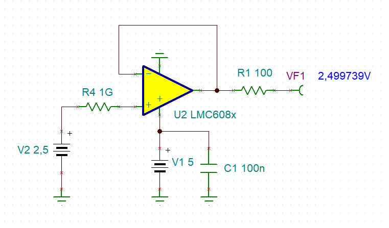
  • This could be used as a test circuit:

    isee_lmc6081_1.TSC

    Keep in mind that even with infinite input resistance of OPAmp the voltages "V2" and "VF1" may differ by +/-5mV caused by the voltage drop of input bias current of "LMC6081" across "R4" and the input offset voltage of OPAmp.

    If the input resistance of OPAmp is considerably lower than 10T, the input resistance can be calculated (or estimated) by the voltage division or "R4" in combination with the input resistance of OPAmp.

    Kai

  • I fully agree with Kai about meaningless reading of floating amplifier.  Also, de-soldering can destroy the op amp.  As far as the test setup goes, one could use what Kai show above as long as you account for the thermal noise of 1G resistor: Vtot = (4uV/rt-Hz*(1.57*1.3e6)^.5 =  5.7mVrms or 34.3mVpp.

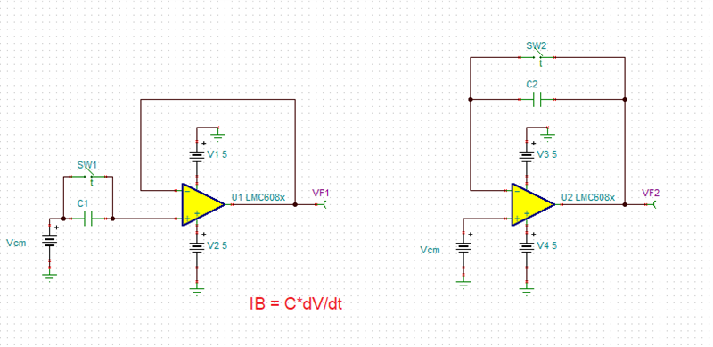
    One could also use the setup shown below and by measuring the change of the output with time (slope - dV/dt) back calculate the IB for different Vcm voltages.

    Having said that, this is a challenging exercise and I'm not clear why you are trying to measure what is already specified in the datasheet.

  • Andreas, I'll close this thread for now.  If you have further questions, please reply to this post or open a new one.