This thread has been locked.

If you have a related question, please click the "Ask a related question" button in the top right corner. The newly created question will be automatically linked to this question.

OPA547: Current Limit Tolerances

Part Number: OPA547
Other Parts Discussed in Thread: INA106

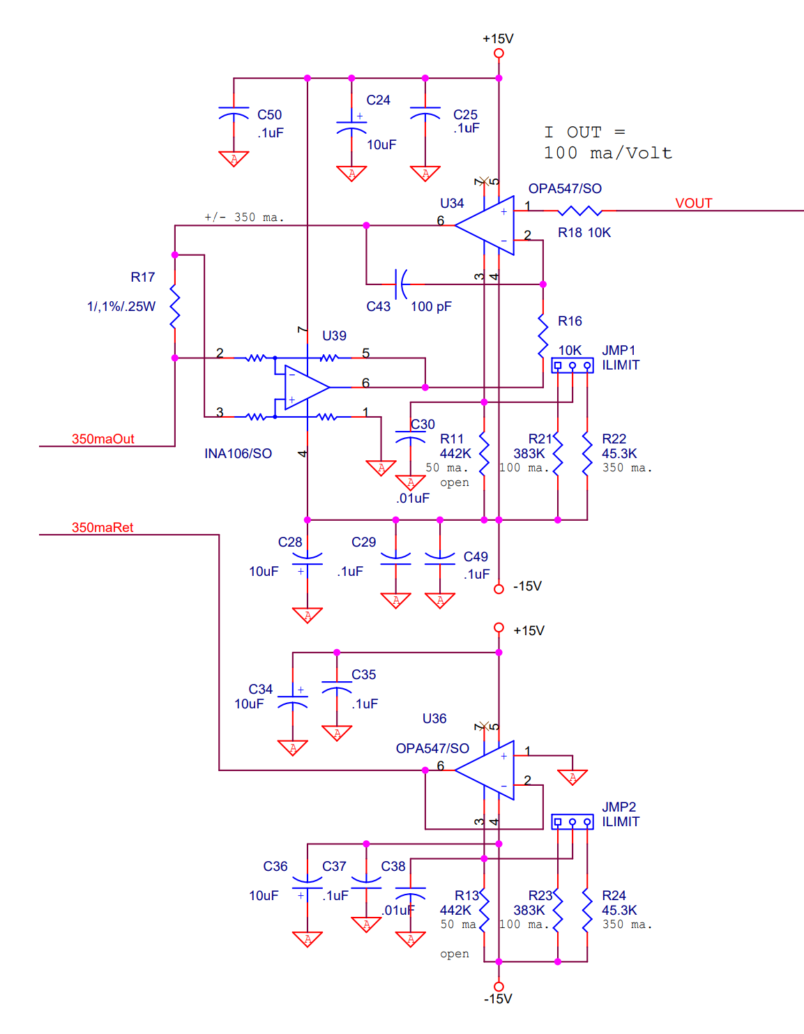
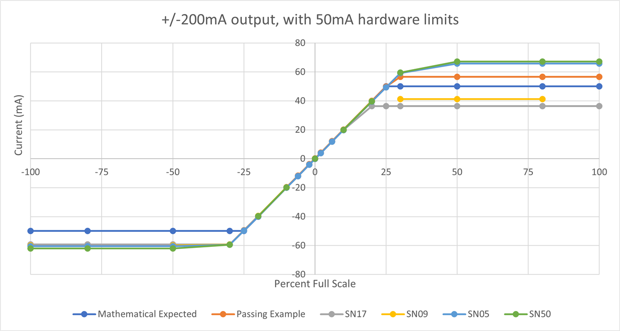
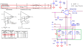
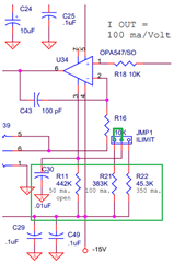
We are using the OPA547 as part of a voltage controlled current source on an output card on one of our controller systems. We supply the OPA with +/-15V. We have three resistors, configurable via a jumper, to select RCL. The configuration in question (the only one we currently use and test for) is 442kohm, which limits the current to 50.15mA (50mA). For our purposes, a card will pass if it properly limits current to 50mA, +/-10mA.

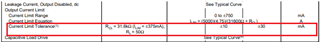
We recently received a batch of these boards and several fail our tests due to currents either lower than 40mA or greater than 60mA. What are the current limit tolerances on the OPA547 with respect to the value(s) of RCL assuming a constant supply voltage? The datasheet tells us on page 3 that when the current limit is set to 375mA that the maximum deviation is +/-30mA. Assuming a linear relation (this might be the problem), extrapolating down to 50mA results in a tolerance of +/-4mA, which is much smaller than the values we sometimes read.

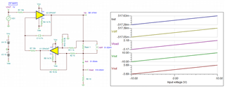
Below is the section of the schematic in question. VOUT is generated via an ADC which outputs +/-10V through a digital potentiometer which sets the gain to the appropriate value to reduce the voltage accordingly (VOUT is also used for a voltage controlled voltage source that must output up to +/10V, not shown).

Perhaps our problem is not because of the tolerance, but some other issue; if you see anything else that could cause our test to fail, let us know.

  • Hi GCTS, 

    Perhaps our problem is not because of the tolerance, but some other issue;

    Please tell us what are the component or voltage settings for the 3 markings circled in green. 

    If I read your description properly, you are saying that the circuit's output constant currents are controlled by the JMP1 and JMP2 current limiting resistors or the combinations of the Rcl or the adjustable current limiting resistors by the 3 pins. 

    This is voltage-to-current converter. At VOUT input node, the input is specified at 100mA/V. If you want to drive 350mA in constant current, then VOUT= 3.5Vdc, if the constant output current is 100mA, then VOUT or the voltage input should be 1V, where VOUT is the node from your schematic.  The Rcl is used to protect OPA547 as overcurrent protection for the op amp, and the constant current source should not be operated under the current limiting feature. It should be regulated under the current feedback circuit or via U39.  

    I put together a similar circuit and the linear input region is from -1.5V to 1.5V in V-to-I conversion. I need to know what is the load for the constant current driving application. 

    OPA547 E2E Iconst 05012023.TSC

    If you have other questions, please let us know. 

    Best.

    Raymond

  • Please tell us what are the component or voltage settings for the 3 markings circled in green. 

    R17 is 1 ohm.

    Vout can be up to +/-10V, but during current control, is lowered down to smaller ranges; for example, when we desire +/-40mA output, the range is +/-400mV

    While the board was designed for various current outputs, we typically only use 40mA servo valves with 40ohm loads (and thus set the hardware current limit to 50mA and Vout range to achieve +/-40mA).

    For testing the hardware current limit, we change the voltage range to achieve +/-200mA output (+/-2V) and measure current output at the extreme ends of the voltage input range. We've done this two ways, one by simply reading the current value via a multimeter and the other by giving the output a load of 2 ohms and measuring the voltage across it (either with a multimeter, or one of our system's input cards) and calculating current.

    If I read your description properly, you are saying that the circuit's output constant currents are controlled by the JMP1 and JMP2 current limiting resistors or the combinations of the Rcl or the adjustable current limiting resistors by the 3 pins. 

    Yes, but the 100mA and 350mA current limits aren't typically used. We usually only use the 50mA limit, and thus, is the only thing we test for.

    My understanding behind the original design and intent of this circuit was to protect the servo valves from higher than rated currents under the condition that the end user did not set up our software correctly during a test. I believe we also used to use 50mA servo valves before they went obsolete, replacing them with 40mA ones, hence why the board was designed with a 50mA limit. This all was before my time at the company.

    Additionally, below is a chart showing various responses for some boards from our latest batch. There's the Mathematical Expected values, assuming everything is ideal, the Passing Example, a board that passed our tests, and four boards that failed our tests. The negative end seems to be consistently limited to approximately -60mA (rather than the expected -50mA), but the positive end differs from anywhere from 36 to 67mA.

  • Hi GCTS, 

    I believe we also used to use 50mA servo valves before they went obsolete, replacing them with 40mA ones, hence why the board was designed with a 50mA limit.

    With R11 = 442kΩ, the I_lim is configured for 5000*4.75/(31.6kΩ + 442kΩ) = 50.15mA. Since the current limit tolerance is specified up to ±30mA at 25C, the circuit's current limit should be configured at least for ±80mA, likely for ±100mA range for the condition, if the application is taken into account a full operating temperature range. 

    With I_lim = ±50mA, OPA547's current will be operated as low was ±20mA and as high as ±80mA at room temperature. The OPA547 is operating what is expected from the graph you presented.

    OPA547's datasheet indicates that the I_lim feature is not precise and I_lim will work in a range. In order to guarantee the I_lim = ±50mA, the applicable current limit circuit will set Rcl to approx. 205kΩ.

    If you parallel R11||R21 resistor (parallel R11||R21 is 205kΩ) or short JMP1 jumper pin1 and pin2, the circuit will have I_lim = 100mA, so the option is there on the board. 

    If I understand the application correctly, the user is using the OPA547's I_lim feature to limit the output current, even though the OPA547's output current may be higher than the programmed or specified values from the system's ADC. The I_lim feature was more or less working satisfactorily from the previous lots, now it is not working properly due to I_lim variability in the recent OPA547 lots.  At least, the circuit is not working the same way as before. 

    R17 is 1 ohm.

    Vout can be up to +/-10V, but during current control, is lowered down to smaller ranges; for example, when we desire +/-40mA output, the range is +/-400mV

    I did a quick check: The circuit does not have 100 mA/V conversion ratio. It is more like 51 mA/V. In other words, the circuit will generate ~±100mA for ±2V. Also, there may be instability issues in the original circuit. If you wan to point out the issues, you need to provide the full schematic on the section. 

    This is the public forum. You may consider to contact me via Private E2E messaging forum, and we can resolve the rest of the issues there.  

    Best,

    Raymond

  • Since the current limit tolerance is specified up to ±30mA at 25C,

    I was under the impression that this tolerance specification in the data sheet was only an example given at a limit of 375mA, and perhaps at smaller limits (50mA) the tolerance could be smaller too (4mA; same percent tolerance of 8%). But, if what you are saying is true, regardless of the current limit, the (maximum) tolerance is a flat value of +/-30mA.

    If I understand the application correctly, the user is using the OPA547's I_lim feature to limit the output current, even though the OPA547's output current may be higher than the programmed or specified values from the system's ADC. The I_lim feature was more or less working satisfactorily from the previous lots, now it is not working properly due to I_lim variability in the recent OPA547 lots.  At least, the circuit is not working the same way as before. 

    Typically, we would set the hardware limit based on the specifications of the system, and the user would then (typically) only adjust the output range via software. We do not expect users to move the jumper themselves. But, yes, this feature was working satisfactorily in the past, but this most recent lot has some boards with too high variability.

    I did a quick check: The circuit does not have 100 mA/V conversion ratio. It is more like 51 mA/V. In other words, the circuit will generate ~±100mA for ±2V.

    Strange. As mentioned earlier, the circuit also has a nearby voltage controlled voltage source derived from the same Vout signal (the output is 1:1 to the input, more or less). When measuring the voltage on this output, we read nearly 400mV when the software is configured to output 40mV on the current side. One difference we noticed with your circuit is the use of two OPA547s for the Out(put) side, rather than one and an INA106. There are two OPA547s total, but the other is used for the virtual ground on the Ret(urn) side.

    Also, there may be instability issues in the original circuit. If you wan to point out the issues, you need to provide the full schematic on the section. 

    This is the public forum. You may consider to contact me via Private E2E messaging forum, and we can resolve the rest of the issues there.

    We might take you up on this offer. I will have to check with my higher-ups before proceeding.

  • Hi GCTS, 

    perhaps at smaller limits (50mA) the tolerance could be smaller too (4mA; same percent tolerance of 8%)

    The example represents 50% of the rated current in OPA547. The current limit tolerances represents typical and max. errors over the entire range and should not be linearized. The datasheet would use percentage or other representation to present the errors, if it is linearized in percentages.   

    We do not expect users to move the jumper themselves.

    If the firm is able to jump pin1 and 2, then the coarse current limit ranges will be configured at approx. ±100mA. You may have to change the input voltage to provide more precise current limit. Since this is V-to-I controller, the current limit setting can be regulated very precisely by varying the input voltage (VOUT in the schematic). OPA547 is unable to provide the specific tighter current limits, especially at the lower current limit range. 

    In the OPA547's datasheet, the variation of the current limit tolerances are specified, and parts to parts or lots to lots variations will be a part of the semi process, unless much tighter screening process is implemented for a specific set of performance variables.  

    Regarding to additional assistant, please send me a "friendship request" via E2E forum (if you need further support), which is our private support messaging forum. Or I can provide you with the internal email after we established the communication.

    Since I do not have your complete schematic, my simulation is based on the information that I have, and it may or may not represent what the actual system is doing per the application. 

    I am going to close this inquiry. If you have additional questions, we can resolve it via E2E private messaging or the internal email.

    Best,

    Raymond 

  • Since I do not have your complete schematic, my simulation is based on the information that I have, and it may or may not represent what the actual system is doing per the application. 

    I am going to close this inquiry. If you have additional questions, we can resolve it via E2E private messaging or the internal email.

    Understandable.

  • Hi GCTS, 

    Please contact me E2E private messaging or our internal email. We have accepted your invitation via E2E private forum. 

    Best,

    Raymond