This thread has been locked.

If you have a related question, please click the "Ask a related question" button in the top right corner. The newly created question will be automatically linked to this question.

INA180-Q1: Analog output stuck to 0V

Part Number: INA180-Q1
Other Parts Discussed in Thread: INA180

Dear tech support, 

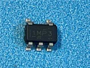
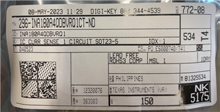
we use the INA180A4QDBVRQ1 component in one of our product - the product is validated and it is currently in production (hundreds of units in the last 3 years - Motorsport application).

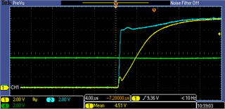
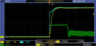
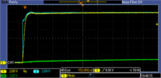
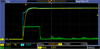
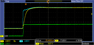
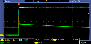
In one of the latest production batch, we noticed a "strage" behaviour of this component. Sometimes, at power up, the IC analog output gets stuck at 0V, even though the current is correctly provided to the load and running through the shunt resistor (R99).


The implemented schematic is the following.

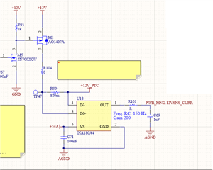
The only way to "restore" the INA to properly work is to remove and apply again the +12V power rail (TP47). Please consider that on the PWR_MNG.12VSNS_CURR is mouted a 10uF ceramic capacitor.

Are you aware of this phenomenon? Do you have an idea why this happens and how to fix this? 

We also purchased on DigiKey new components and test them out, but the issue is the same. Did something changed in the IC design?


Thanks in advance,

Andrea

  • Hello,

    No nothing has changed on the INA180. If you could give me the lot number on the Digikey package I can verify if these are genuine parts.

    Has anything else changed in your circuit? If you power-cycle the board does the issue persist? Would it be possible to verify the VS voltage and VCM voltage on a scope shot (during power-up with and without failure)?

    Regards,

    Cas

  • Dear Cas,

    thanks for your feedback.

    Please find here below all the measurements - with and without failure.

    SCREEN 1 - WITH RESISTIVE LOAD CONNECTED - NO FAILURE

    CH1: INA180 - Pin 4 - IN- (YELLOW)

    CH2: INA180 - Pin 3 - IN+ (BLUE)

    CH4: INA180 - Pin 5 - VS (GREEN)

    The IC supply line (+5V) is up ~2 seconds before activating the output power line (+12V)

    SCREEN 2 - WITH RESISTIVE LOAD CONNECTED - NO FAILURE

    CH1: INA180 - Pin 4 - IN- (YELLOW)

    CH2: INA180 - Pin 3 - IN+ (BLUE)

    CH4: INA180 - Pin 1 - OUT (GREEN)

    At the beginning the output is high saturated, and after 40us if works nominally

    SCREEN 3 - WITH RESISTIVE LOAD CONNECTED - NO FAILURE

    CH1: INA180 - Pin 4 - IN- (YELLOW)

    CH2: INA180 - Pin 3 - IN+ (BLUE)

    CH4: INA180 - Pin 1 - OUT (GREEN) FILTERED, post RC (R101, C69)

    The RC filter works fine, filtering the OUT signal.

    SCREEN 4 - WITHOUT RESISTIVE LOAD - NO FAILURE

    CH1: INA180 - Pin 4 - IN- (YELLOW)

    CH2: INA180 - Pin 3 - IN+ (BLUE)

    CH4: INA180 - Pin 1 - OUT (GREEN)

    The output signal gets low after the 10uF capacitor is charged - no load is connected.

    SCREEN 5 - WITHOUT RESISTIVE LOAD - !!FAILURE!!

    CH1: INA180 - Pin 4 - IN- (YELLOW)

    CH2: INA180 - Pin 3 - IN+ (BLUE)

    CH4: INA180 - Pin 1 - OUT (GREEN)

    Error condition: the OUT signal stays high for more than 40us, and then slowly goes to 0V. The external load is not connected. 

    The two plots have different time scaling, in the second plots you can see the output discharge phase.

    Please note that in this condition the Vs is up way before the external load is powered. 

    Thanks,

    Andrea

  • Regarding the missing information:

    • No, our design didn't change in the last 3 years. We are now checking the passive components with respect the previous production batches, but all the relelevant components are the same.
    • If we power-cycle the board, it's like flipping a coin: sometimes the fault condition happens, but it seems random.

    • The IC marking is the following:

    Do you need more info about the DigiKey part?

    Thanks,

    Andrea

  • Hello, 

    Yes if you can provide the lot number on the digikey esd bag label there should be a lot number. 

    Also is it possible to get a Vs with IN+ and IN-  and a failure you show here Vout?

    I will look this over.

    Regards,

    Cas

  • Dear Cas,

    here the DigiKey info:

    In case of failure, the Vs is stable and high (+5V) some seconds before the +12V are applied to the load.

     With respect to SCREEN 5, the Vs has the same behaviou shown in SCREEN 1.

  • Hello,

    Okay there are problems with latch-up when the device has a floating Vs and a Vcm is applied I just wanted to check this was not happening. I will continue to look into this problem and the authenticity of the INA180. Expect a reply within the week.

    Regards,

    Cas

  • Hello,

    It looks like the common mode when there is a failure goes from ~2.7V to 12V while on the no failures the Vcm goes from 0 to 12V. What is 12V_PTC rail powering? 

    Regards,

    Cas

  • Hi there,

    12V_PTC rail powers two external pressure sensors (the nominal current absorbed for the two sensors is ~5mA). The 12V_PTC rail has also a 10uF bypass capacitor.

    Understood your point on the ~2.7V starting voltage: we now double check the Vs voltage.

    Thanks,

    Andrea

  • Hello,

    The top markings are correct on the part so they most likely are genuine parts. Let me know about the 2.7V on the common mode for the failure.

    Regards,

    Cas

  • Hello,

    I have not heard back from you. I will assume you have fixed the problem. I will close this thread for now. If anything comes up just reply below.

    Regards,

    Cas