This thread has been locked.

If you have a related question, please click the "Ask a related question" button in the top right corner. The newly created question will be automatically linked to this question.

INA201: Regarding to the potential difference between pins

Part Number: INA201
Other Parts Discussed in Thread: INA281, INA310B

Hello team,

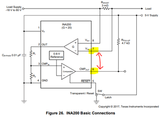
I received a question from the customer. This is a rudimentary question, but for example, in Figure 26, there is a maximum potential difference of 75V (Load supply 80V - 5V supply) between pins 6 and 7, but is this OK? The customer was concerned about this point because of the small pin pitch of the VSSOP package.

Regards,

Masa

  • Masa,

    The INA201 has a max VCM of 80V, so the customer should ensure that the voltage of the IN+ pin does not rise above 80V, or the device may experience EOS.

    We don't generally have problems due to insufficient clearance, but we most likely will not comply with industry standards the customer may be using. The customer could use a PCB coating or use the larger device package to mitigate the risk and/or comply with their standards.

    Something the customer might consider is using a different chip - the INA310 is a drop in replacement for the INA201 with a higher Vcm rating, so there is much less risk of EOS if the customer is planning to operate at 80V. If the customer doesn't use the comparator, the INA281 pinout features high voltage pins on the opposite side of the device from the low voltage pins.

    Let me know if you have any further questions,

    Levi DeVries

  • Hello Levi,

    Thank you for your explanation. I will introduce INA310B as well.

    Regards,

    Masa