This thread has been locked.

If you have a related question, please click the "Ask a related question" button in the top right corner. The newly created question will be automatically linked to this question.

LOG114: TINA-TI simulation error

Part Number: LOG114
Other Parts Discussed in Thread: TINA-TI, OPA2335

Hi Team,

Can you please help us with our customer's inquiry below.

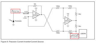
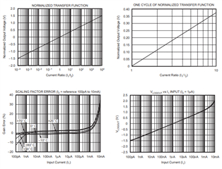
I would like to ask about the logarithmic amplifier log114 datasheet, which converts negative current into positive current input to the log114 for amplification.

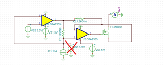
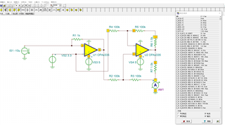
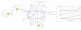
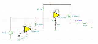
Is the current inversion with OPA2235 1:1? I simulated the circuit with TINA-TI, but the current output is not correct.

Simulation file to change the size of the current source, the OPA2335 output current size remains unchanged, such as input 10na, the output through the amperemeter shows 86.5uA

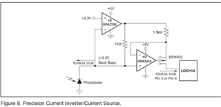
Can you help to verify or give me a correct current inverse current simulation file, I try to verify the simulation with TINA-TI on my computer, the circuit diagram I simulated is from the log114 Figure 9. Precision Current

Inverter/Current Source.

Sorry, I also want to ask a question, I input reverse current source, in the OPA2335 side, but also need to add bias voltage 3.3v well, if my current is less than 10na, can also use this current inverter for reverse, the manual

circuit diagram is given in 10nA to 1mA

OPAx3225 - autosav.TSCOPA2335_BSH203.TSC 

Regards,

Danilo

  • Hi Danilo,

    The circuit the customer is referring to is here:

    There are 2 problems with the circuit given in the tina files - first, there should not be a voltage source connected to the current source IS1:

    The second problem is that the FET shown is way too large to support this function; the Ids leakage is high and the threshold voltage is also very high, it won't work for a low voltage (5V) solution.  The diagram shows the "BSH203" - I can't find a model of the "BSH203", but if you can find a PSPICE model of that FET or similar, changing it out should fix the problem. 

    Let me know if there's any other questions here.

    Best Regards,
    Mike

  • Thank you for your reply,

    Since I couldn't find the BSH203 model, I switched to the log114 datasheet  Figure 9. Precision Current Inverter/Current Source

    The current inverter conversion circuit was reworked and simulated.

    • Current source input minus 10 µA   The current value displayed on the output measured with an amperometer is not 10 microamps
    • How to solve this problem, is there a problem with my simulation circuit, please point out, can you give a tian simulation model that you verify is correct
    • If the input current is negative 1nA, can this precision current inverter circuit be converted to a positive 1nA current, and what problems should be noted?
    • 8424.OPAx3225 - autosav.TSC
    • This is tia model
  • Hi cpin,

    If the input current is negative 1nA, can this precision current inverter circuit be converted to a positive 1nA current, and what problems should be noted?

    The Log114 has a wide dynamic range up tp 8 decades from 100pA, and it should work well and accurately at 1nA range. 

    Here is the full simulation:

    LOG114_Cur_inv 06152023.TSC

    Here is an example that is close to 1:1 inversion. 

    If you have additional questions, please let us know. 

    Best,

    Raymond

  •  Hi Raymond,

      Thank you for your reply and answer,Your reply and giving the circuit simulation model is very good and very helpful for me

  • Cpin,

    In addition to Raymond's sim, here is a working Howland pump current solution (the second configuration is based on the Howland Current Pump).

    The problem with the sim. you created was that the current measurement connected to ground.  This meant that in order to work properly, the amplifier needed to function also very close to ground, but, that forced the amplifier to work outside of the output linear range.   In the sim. below, I moved the current measurement node up 0.5 V, so the amplifier's output was operating in the linear mode.  

    Also, I am not actually sure why the LOG114 data sheet uses 1.5k resistors in the output, it makes more sense to me to use 1k resistors so that the current is copied in a 1:1 ratio.  The TIA at the input uses 1k to convert the current to voltage, and the Howland pump will perform the opposite (output current = input voltage/1k).  I made this change in the included simulation.

    Note that it will be very difficult to achieve 1 nA resolution with the Howland solution.  The offset voltage error of the amplifier alone with create a significant current error.  If you have 1 uV of offset voltage with the included simulation, this will convert to 1*2/1k = 2 nA of error current.  You could use larger resistors at the output, so that the amplifier offset voltage has less of an impact, but then the total range that the circuit can be used in is much lower.  For example, if the 1k resistors moved to 10k, then 3V on the input results in 300 uA of output current, instead of 3 mA.  This will limit the maximum current the circuit can output.

    Hopefully these simulations give you a good way to understand the tradeoffs for your particular circuit. Let us know any other questions.

    Regards,
    Mike

    LOG114_Current_Inversion_Howland.TSC