HI everyone,
I will be happy to get some help with a simulation from pspice project I am doing.
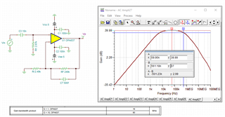
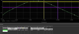
I assembled a scheme witch gives me gain of approx. 40DB
My FL is approx.. 6KHZ and FH approx. 600KHZ.
But i have a problem that i nedd the slope at the ene to be -20db/dec and it is -40db/dec
and my ROUT to be 13K ohm and it is 3Kohm.
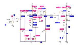
the scheme is: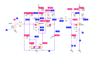
and the sym is
plese help me to find my mistake
much regards.