This thread has been locked.

If you have a related question, please click the "Ask a related question" button in the top right corner. The newly created question will be automatically linked to this question.

TLV9001-Q1: Differential-to-single ended 0-3.3V Conversion for highly cost sensitive application

Part Number: TLV9001-Q1
Other Parts Discussed in Thread: INA351, REF2033, TLV7022,

Hello All,

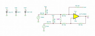
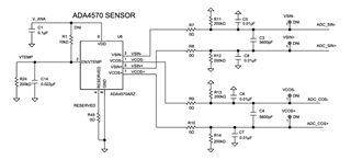
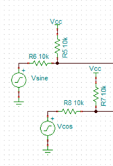
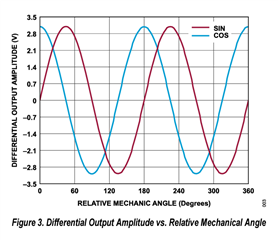
We need urgent guidance on converting differential Sine & Cosine signals of the ADA4570 AMR Speed sensor into Single-ended 0-3.3V input for ADC.

  1. What is their gain requirements? 1 or 0.9
  2. What is their input/output voltage range? Bipolar 3.3V Signal
  3. What is their power supply requirements? Single-ended 3.3V or 5V
  4. What will the load be at the output of the amplifier? ADC
  5. Are there any distortion or noise minimum requirements? Least noise for cos sensitive application

We have selected INA351 with internal Vref Buffer for its low cost, kindly suggest any alternatives or more integrated solutions for this with some reference design.

Thanks in advance, Regards.

  • Hello Shreeneet, 

    Welcome to e2e :) 

    I would reference the Difference amplifier (subtractor) circuit. I have adjusted the solution a little bit to fit your system requirements: 

    e2e_SBOA274.TSC

    I added the combination of R5/R6 and R7/R8 to scale the input before taking the difference.

    As you can tell from the question you referenced earlier, the solution may have capacitors added as mentioned in Design Note #5. 
    Additionally, the noise can be reduced by using smaller resistor values. 

    All the best,
    Carolina 

  • Hello Caro,

    Thank you for your quick suggestions.

    I am unable to find any inventory for Vref 1.65V - REF2033, are there any alternative updates we can make in the design?

    Ideally, if we can use the internal Vref from the MCU which is 2.0, 2.5 or 2.048 Volt.

  • Hey Shreeneet, 

    Vref is simply midsupply, you can just use a resistor divider from V+/V-: 

    All the best,
    Carolina

  • HI Shreeneet,

    I am Bhuvanesh, Systems Engineer with TI. I would like to double check if these "sine" and "cosine" signals would only be a maximum of 90 degrees out of phase. If they could be 180 degree out of phase at any instant (power up for example), the amplifier may hit the rail.

    Also, I guess these signals don't seem to be coming out of AMC device. I ask this because the related post is about the AMC. Are these sine and cosine signals coming out of some encoder circuitry somewhere ?

    Best Regards,

    Bhuvanesh

  • Hello Bhuvanesh,

    Yes, these waves are generated by AMR Sensor ADA4570.

    These are not coming out of AMC devices, I have mis-referenced it to the original question.

    Do you have a simplified & enhanced robust suggestion for this circuit? I am new to Analog designs myself, and we need to implement this for a highly cost-sensitive application focused on Micro & Small Scale Industries in India. The ADC under discussion is for STM32G474 MCU.

    All help shall be highly appreciated.

    Regards.

  • Hi Shreenet, 

    Could you share the maximum differential voltage that you might expect between the sin and cosine waves ?

    That would help our team check if the solution that was proposed earlier needs to be adjusted or not.

    Best Regards,

    Bhuvanesh

  • Hello Bhuvanesh,

    Vdd here shall be between 3.3V or 5V, we would like to prefer 5V Vdd to improve the noise immunity from the sensor to the ADC. We have selected the ADA4570B sensor for our use case.

    We are looking for a highly integrated solution to drive 12-bit ADC built in our MCU. We have a total of 5 12-bit ADCs with both single & differential inputs available. The distance between the sensor & the MCU ADC is about 1m which shall be powered by 24AWG STP cables. the ADC input impedance is 15k Ohms.

    Let me know what additional details would help you propose a cost-optimized adjusted solution.

    This solution if for measuring the slippage in pulley transmission drives used in industrial equipment & is a highly cost-sensitive use case.

    Regards.

  • Hey Shreeneet, 

    I believe we are good to go for the earlier solution, it can be used at 5V also (make sure VREF is midsupply = 2.5V). 

    With 77% of the supply voltage from the specification shared is around 2.475V, the proposed solution is at ±1.56. It is likely that the resistor values will have to be tweaked based on real world values. Please leverage the simulation profile earlier to assist. 

    All the best,
    Carolina

  • Hello Caro,

    Thank you for the follow-up update, the inputs channels are differential Sine & Differential Cosine inputs. So we have a total of 4 inputs & we wish to drive a ADC that accepts 0 to 3.3V input.

    Do you think given this use case, we can also eliminate the buffer altogether as the ADC on our MCU accepts differential inputs?

    Kindly guide.

  • Hey Shreeneet, 

    The design no longer requires the difference between the cosine and the sine? 

    All the best,
    Carolina 

  • Hi Caro,

    Attaching the Sensor schematic for clarity. This is for a speed-sensing use case where we want to measure the speed of the shaft.

  • Hey Shreeneet, 

    Thank you for attaching the schematic, could you please let me know if the design requires the difference between the cosine and the sine? 

    All the best,
    Carolina 

  • Hello Caro,

    Here is the step-wise description of what we have to do with the sensor signals:

    1. Sample both the sine and cosine signals with an ADC.
    2. Filter the signals, if necessary, to reduce noise.
    3. Calculate the ratio of the sine to cosine signals.
    4. Compute the arctangent of this ratio to find the magnetic field's angle.
    5. The time derivative of the angle will give us the speed.
    6. Use the sign of the sine or cosine (depending on the mechanical setup) to determine the direction of rotation.

    So we essentially want to accurately measure the frequency of both signals at it's least (primary use case). and then compute the arctangent to estimate the angular position of the shaft (rare use case). Offset & gain errors might not have any impact on the frequency measurements of the sine & the cosine signals. Also the sensor shall be powered with a 5V supply and hence we need to make sure the differential signal is within the ADC's 0-3.3V range.

    We are looking for a highly integrated solution for this with a cost-optimized approach. We want to convert the individual differential Sine & Cosine into single-ended signals that we can feed to the ADC on our MCU. Or guidance on input circuitry for directly interfacing the differential signals (with RC filters) into the ADC if the cost of differential to single-ended is high. The ADC has an input impedance of 33kOhm and accepts 0 to 3.3V input swing.

  • Hey Shreeneet, 

    Understood, so the difference is not taken in a discrete circuit instead it is done in the ADC. I recommend just to scale the inputs to the ADC, here is a resource: 

    [FAQ] Voltage scaling for almost any application (single ended)

    This is what I had done earlier in my suggested solution with a pair of resistors: 

    All the best,
    Carolina 

  • Hello Carolina,

    Thanks for the updated suggestion.

    1. To confirm, can we directly drive the 33kOhm ADC on our MCU with this sensor signal?
    2. Can we use some low-cost OpAmp implementation for LPF as well as Unity gain buffer configuration to isolate the MCU & the ADC?
    3. As the Offset & the gain errors shall have virtually no impact on the frequency measurement, we can use low-cost OpAmps
    4. Do we have any low-cost integrated solutions with inbuilt resistor networks in unity gain configuration?

    Kindly guide us with your suggestions as there shall be a 1m long cable from the sensor to the ADC that shall be carrying these Sine & Cosine signals. And we wish to implement a suitable RC-based LPF for attenuating high-frequency noise. Our primary frequency of interest shall be no more than 10kHz. So we would like to block signals/noise above 10kHz using the RC filter.

    (Also both the SINE & the COSINE signals are differential signals)

  • Hello Carolina,

    As we are primarily interested in measuring the frequency of the SINE & the COSINE waves, can we also use TLV7022 comparator to detect & trigger at zero-crossovers & then install a Schmitt-triggers at the MCU end of the cable to improve the signal? We can directly feed this square wave to the Quadrature Encoder Interface of the MCU thereby offloading the CPU from these computations.

    Kindly suggest the most optimal Comparator based Zero-crossover based solution that can help us transfer 0-5V square wave to 1m distance from the sensor to the MCU and possible use of Schmitt-trigger at the MCU end to improve the signal quality.

  • Hey Shreeneet, 

    Yes, I would use the TLV9001-Q1 as that is the lowest cost automotive single channel amplifier. 
    I would use it in a buffer or a LPF, here are both circuits respectively: 

    We also have the filter designer tool: 

    Filter Designer | Design Resources

    It is likely that an Riso or and Riso-dual feedback will have to be implemented to stabilize the output of the op amp due to the capacitance of the 1m cable and the charge bucket for the ADC. This can be calculated through theory and simulation taught in these videos in this link: https://www.ti.com/video/series/ti-precision-labs-op-amps.html

    Under Stability: 

    If you need me to calculate the Riso or and Riso-dual feedback (depending on your need for DC accuracy), I can do that just let me know but the resources should help you do it yourself.

    As for the comparator question, please start a new thread (you may reference this one), in order for it to be assigned correctly to the comparators team, I only cover general purpose op amps.  

    All the best,
    Carolina