This thread has been locked.

If you have a related question, please click the "Ask a related question" button in the top right corner. The newly created question will be automatically linked to this question.

OPA2992: distortion at 1MHz

Part Number: OPA2992

Hi team,

When customer powers the OPA2992 with +/- 5V and try to pass a 1 MHz signal of a few volts in unity gain then they see this:

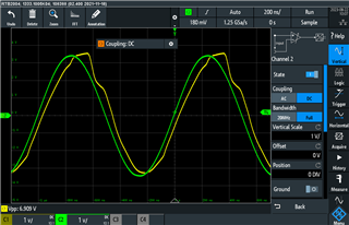
Green is the input wave; yellow the output wave.

It looks like that this distortion occur from a slew rate of 6V/us and higher.

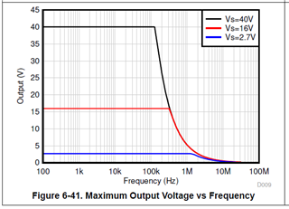
How can they know from the datasheet that this signal is distorted?

BR,
Stefan

  • Hello Stefan,

    The 7Vpp sine is above the red/black line at 1MHz which is about 5Vpp. 6-41 is in the data sheet.

    You need a much faster op amp to get a clean output sine. 

    It takes significant input difference (IN+ - IN-) voltage [VID] to get the required slew rate. Required peak slew rate is pi*F*Vpp = 22V/us

    As input slew rate changes from 0V to +/-22V/us, the VID to create the output slew also changes and that change isn't linear.

    The difference between input signal and output signal is the VID needed for the output slew rate.

    Slew application note for more details; [APP] Ramping Up on Slew Rate

  • Hi Ron,

    customer was confused by this plot because it does not state that the voltage is the pk-pk voltage.

    Customer expects that the slewrate boost circuit is active in this area, but how can they know that this is the case?

    BR,
    Stefan

  • Stefan,

    The Vpp is subtle but easily discernible. At 100 Hz the output voltage is the as the whole supply voltage; therefore only Vpp is possible.

    They can know the op amp has slew boost using the four test methods described in the application note. The multiple sudden changes in the output slew rate (in 1st waveform of this thread) are a good indicator.