This thread has been locked.

If you have a related question, please click the "Ask a related question" button in the top right corner. The newly created question will be automatically linked to this question.

TLV3501: design questions about TLV3501

Part Number: TLV3501
Other Parts Discussed in Thread: SN74AUP1T17

Dear Team,

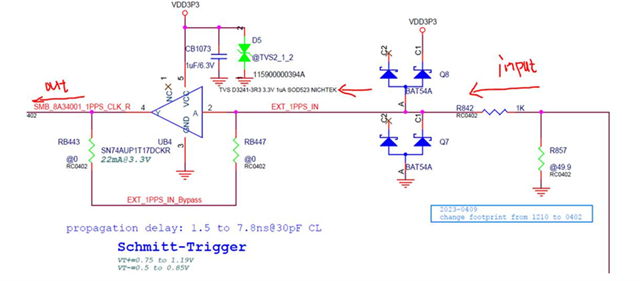
Any advice for the comparator design about TLV3501?

Regarding the sqr2sine design, we found a lots of harmonics at 30/50/70/90Mhz when using square as output waveform, and it also caused EMI radiation emission failure. It would a solution to replace with sine wave, and these harmonics will be eliminated. Following is our expected structure.

Source -> 3.3V square wave clock @10MHz -> sqr2sine circuit -> 5V sine wave clock @10MHz -> SMB connector -> external cable

Many Thanks,

Jimmy

  • Hi Jimmy,

    Could you tell us more about your application and system requirements? Where is the comparator being used in this structure? to generate the 3.3V sq wave clock? And what would be the input signals that goes into the comparator?

  • Hi Chi,

    We appreciated your great support.

    1. Square wave to sine wave:
    sqr2sin is to solve the square wave EMI low frequency harmonics 30/50/70/90Mhz, please provide suggestions on this part, thank you!

    2. Design the comparator to support 1.2V and 5.5V 1PPS input swing:
    Output will go to WANPLL, the requirement is 3.3V swing@ 1PPS, Vmin=0
    The original design uses SN74AUP1T17, because the delay and VT+=1.19 (if the input is 1.2, the margin will be very large), so I want to use the comparator design
    Do you have any suggestions for reference, thank you!

    Many Thanks,

    Jimmy

  • Hi Jimmy,

    I am assuming that you meant the input could be from 1.2V-0V or 5.5V-0V. Is 50% duty cycle required?  IF so, I am not sure this is doable as the reference of the comparator will need to be set to the midpoint of the input signal; but this would be limited by the 1.2V signal and midpoint of 1.2V would not be the midpoint of the 5.5V signal. For example, the reference could be 0.6V and the output will be 50% duty cycle if the signal is 1.2V but the comparator output would not be 50% for a 5.5V signal. If 50% duty cycle is not needed, then this could work, but you would need to divide down the input signal to accommodate for the 5.5V signal as the comparator is being powered by 3.3V.

  • Closing this post as we hve not heard from you. Feel free to reply if you have any more questions.