This thread has been locked.

If you have a related question, please click the "Ask a related question" button in the top right corner. The newly created question will be automatically linked to this question.

[FAQ] Selecting the Appropriate Pull-Up Resistor for Open-Drain Comparators

Other Parts Discussed in Thread: TLV1821

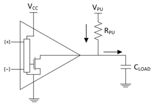
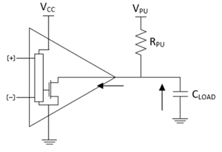
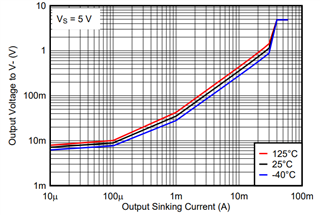
How do I choose the right pull up resistor size when using an open drain comparator? What are the system design considerations?

  • An important design consideration when working with open-drain/open-collector comparators is the selection of the pull-up resistor size. When the transistor is off, current is sourced from the pull-up voltage through the pull-up resistor to drive the output high. Conversely, when the transistor is on, it actively sinks current, pulling the output of the comparator low. Pull-up resistor value selection plays a crucial role in the circuits power consumption, rise time, and output logic level.

    Power Consumption

    A small pull-up resistor has a large power consumption when the comparator is sinking current and the output is low. For example, if we assume Vpu = 5V, Rpu = 1kΩ, and the output gets pulled to GND during output low, the power consumption of the output stage would be Vpu^2 / Rpu, which would be 25mW. On the other hand, if we chose Rpu = 1MΩ, the power consumption would be 25uW.

    Rise time

    A large pull-up resistor will increase the rise time of the output. The rise time of the output is determined by the RC time constant of the pull-up resistor and the load capacitance; a large 1MΩ pull-up resistor would have a slower rise time when compared to a small 1kΩ pull-up resistor. The picture on the left below depicts the flow of current when the capacitor is being charged and the one on the right depicts the flow of current when the capacitor is being discharged. 


    Output logic level

    Here is the output voltage vs. output sinking current graph for the TLV1821. As more current is sunk using a smaller pull up resistor, the output logic low level (VOL) increases. From this graph, we can estimate the output low logic level determined by the output sinking current.  Ideally, the targeted amount of output sinking current should be somewhere in the linear slope region of the curve. For example, with Vpu = 5V and Rpu = 1kΩ, the output sinking current would be somewhere around 5mA. The output low voltage can be estimated to be around 200mV. 


    The maximum pull-up resistor value is determined by the output high leakage current. From the leakage specification, a good estimate of the off resistance of the output transistor is Vpu / Ilkg. This value estimates a maximum pull-up resistance value since a resistance value comparable to the off resistance would introduce a significant voltage drop across the pull-up resistor when the output is high.

    Conclusions

    The pull-up resistor value is a tradeoff between power consumption, rise time, and output logic levels. Compensating for one will detract from the other, so selection of the pull-up resistor depends on system requirements and whichever specification is most crucial. For example, an always-on battery monitoring system would favor a lower power consumption, but a high speed level-translation system would prefer a faster rise time and output logic level.

    Generally, the maximum current through the pull-up resistor is recommended to range between 100 µA and 1 mA to get the best balance between power consumption, rise time, and output logic level.