This thread has been locked.

If you have a related question, please click the "Ask a related question" button in the top right corner. The newly created question will be automatically linked to this question.

XTR116: xtr116

Part Number: XTR116
Other Parts Discussed in Thread: XTR117, XTR111, XTR115

I have a turbine flow meter to measure 0-250 gallons per minute of diesel pumped through filtration. The $415 Instrumart F to I converter failed new, They want $700 to test it, or $560 to replace it. I want to build a new F to I converter using the XTR116 for output. The turbine flow meter has a propeller in a 3" tube with magnets. A proximity detector reads the magnets and creates a sine wave corresponding to flow. It has a K-Factor that shows the calibration as 52.993 pulses per gallon. At full speed 250gpm * 52.993 ppg / 60 sec per minute is 220 Hz should output 20mA, 0 Hz should output 4mA, 200 gpm is around 177 Hz, 100 gpm is 88 Hz.linear scale.

The XTR116 looks perfect for the output, I downloaded the "tiduao7" 2-wire 4-20mA Transmitter reference disign from the TI website. I am looking for suggestion for the front end zero crossing detector for the proximity detector at 30 mV or better, and a micro controller to to the math and output to the XTR116.

Could you please recommend a micro controller for the front end? The entire system of course must consume less than 4mA. Would a MSP430F20xx work for this. The XTR11x has a loop powered 5v regulator, so it would be better to find a microcontroller that operates a 5v that has an analog input to detect the proximity detector in the turbine flow meter.

Thank you,

Robert 

  • Hi Robert, 

    Here are our Frequency to Voltage Converter option, in case that you need it. 

    https://www.ti.com/amplifier-circuit/special-function/frequency-converters/products.html?keyMatch=VOLTAGE%20TO%20FREQUENCY%20CONVERTER

    I am looking for suggestion for the front end zero crossing detector for the proximity detector at 30 mV or better, and a micro controller to to the math and output to the XTR116.

    Enclosed is a simulation example of 0 ≤ Vin ≤ 3.3 to 4-20mA current converter. Per the 2-wire 4-20mA current loop transmitter, we have XTR115, XTR116 and XTR117 that will work for the application. Additionally, we have XTR111 3-wire 4-20mA current loop transmitter, if the input does not meet the 2-wire transmitter's input requirements.

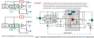
    The differences between 2-wire and 3-wire transmitters are:

    In 2-wire current loop transmitter, the input voltage signal is floating and it is referenced to IRET or pin3 reference node as XTR115/XTR116 or XTR117 ICs, and only one GND reference is allowed and typically is allocated near Vloop or supply side.   

    In 3-wire current loop transmitter, there is not input reference signal requirements. Both input and output signals in XTR111 can be referenced to GND (no input signal constraint requirements). 

    XTR116 0-3.3V to 4-20mA 09282023.TSC

    Could you explain what your 30mV or better proximity detector is about? We have various low power and precision op amps to interface with 2-wire current-loop transmitter application. 

    If the turbine flow meter is able to generate Frequency to voltage signals, 2-wire or 3-wire current-loop transmitter is able to convert the input voltage to current. The input signal does not have to be 3.3V or 5V in Full scale in order to convert to current, so is the current conversion as well. In 2-wire transmitter, 4-20mA current loop is a standard transmission signal. In 3-wire transmitter, it can transmit 0-20mA, 4-20mA or other options to meet an application requirements. I am implying that the input voltage range and output current conversion are sort of flexible, as long as it meets a linear transfer function or conversion requirements per your application. 

    I am not very familiar with MSP430F20x1 product line, but it seems that it can be powered up to 3.6Vdc and it is a low power MCU. The product is supported by a MSP430 team and we can figure it out rather quickly. If you are able to tell me what ranges of mV input signals need to be amplified and convert to the current, I can provide you with a suggestion. There are more than one ways to interface the flow meter signals to current (we may be able to implement the input signal conversion in all analog circuit or via analog --> digital -->analog approaches or something in between ). 

    Here is an application note that may be relevant to your application. 

    https://usermanual.wiki/m/7cba65518c268bfa904900d66e68c86f3893def8c26c014c95cc16d627d466b0.pdf

    Best,

    Raymond

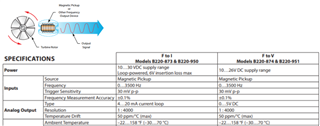
  • I have attached some links to files describing the circuit. It is basically a proximity detector picking up pulses from a propeller in a tube. This turbine is calibrated on a flow bench, and assiged a "K-factor", which in this case, is 52.9930 pulses per gallon (ppg). This is the ac frequency that the proximity sensor is producing during fluid flow. The frequency to converter is programmable to allow for different "K factors". I just need the one K factor.

    So I need input conditioning/amplification of a 30 mV or better ac signal, zero crossing detector, count the frequency and convert to voltage with a microcontroller, then output a voltage to a TI XTR11x for 4 - 20 mA output. The XTR11x is current loop powered, and has a regulated output to power the microcontroller. Perhaps a microcontroller with an analog op-amp input? As stated in the XTRx data sheet, the circuit must consume less than the lower range of 4 mA.

    https://www.instrumart.com/assets/Blancett-1100-lTurbine-Flow-Meter-Datasheet.pdf

    https://www.instrumart.com/assets/Blancett-IFC-datasheet.pdf

    https://kepmeters.com/product/shpfi-m/

    Thanks for your help,

    Robert de Boer

  • Hi Rovert, 

    So I need input conditioning/amplification of a 30 mV or better ac signal, zero crossing detector, count the frequency and convert to voltage with a microcontroller, then output a voltage to a TI XTR11x for 4 - 20 mA output.

    I took a look the F-to-I datasheet, I see that 30mVpp is the voltage trigger variable. So the input signal is square wave like from the Turbine flow meter. What I suggest is to use a comparator to increase the amplitude to 0 to 5V, 0 to 3.3V, 0 to 12V or similar. This is a fairly simply circuit. 

    Once the trigger signals are increased, then you may use one of F-to-V converter to convert the linear relationship, which F vs. Vanalog should be a linear relationship (see the previous reply in F2V part selection). If we have the voltage input, we can convert the Vanalog to current loop transmitter. 

    You may implement the entire signal front end in analog. You may consider the K-factor and other selectable flow sensor parameters after the 4-20mA current loop information is obtained, perform a system calibration and/or GPM conversion. 

    Please let me know if my understanding is correct. I can simulate part of the circuits if you need further assistant. 

    BTW, your approach may resemble to the following block diagram. If you read it through, it is recommending to use digital isolator or PWM signal. This approach is using the digital to analog signal to interface with 2-wire current loop transmitter. It will cost more and PWM to Analog conversion will generate some unwanted errors, unless PWM frequency is high. It is averaging PWM modulated signals through LPF, and then convert the analog signal to 4-20mA current loop.  


    Please let me know if you have other questions. 

    Best,

    Raymond

  • So the signal input is an ac signal from the proximity detector of around 30 mV ac minimum. The turbine is tested that is produces 52.993 pulses (cycles) per gallon. To read gallons per minute is 52.993 / 60 seconds = 0.883216777. The maximum flow is 250 gallons per minute, and should produce 20 mA, the maximum flow is when the proximity sensor reads 220.8 Hz ac / 0.883216777 = 250 gpm.should produce 20 mA. A frequency of 176.6 Hz / 0.883216777 is 200 gpm, half speed is125 gpm * 0.883216777 is 110.4 Hz, and should be 12 mA, the half scale of 4-20 mA. Finally 0 gpm/Hz should produce 4 mA.

    So I guess I am looking for a microcontroller that has an op-amp input that could be configured as an ac signal zero crossing detector, to count the frequency coming from the turbine proximity detector. This microcontroller scales by a factor of 0.883216777 * 220.8 Hz max, and has an ADC to send a value corresponding to 200 microamps to the XTR11x Iinput pin, to output 20 mA full scale. This micocontroller/processor must run off of the XTR11x VREG pin, and must consume much less than 4 mA. The entire circuit is loop powered by 24 VDC to the XTR11x V+/Iout pins.

    Here is something I found, must replace AFE with processsor to detect, scale and output.

    download.mikroe.com/.../4-20ma-click-manual-v100.pdf

    Please let me know if you have a microprocessor that fits these requirements.

    Thanks,

    Robert de Boer

    download.mikroe.com/.../4-20ma-click-manual-v100.pdf

  • Hi Robert, 

    Here is something I found, must replace AFE with processsor to detect, scale and output.
    Please let me know if you have a microprocessor that fits these requirements.

    Please submit an inquiry to our MSP-HSM support team about MSP430 or the latest low power MCU for ultra low power application. I am not familiar enough to provide the recommendation. You would need MCU to operate at 3.3Vdc or 5Vdc, and the full power signal conversion is <3.5mA @3.3Vdc or 5Vdc (if we have 1.8V MCU ultra low power/current MCU, that will be even better). 

    The MCU's power consumption (current is a function of features that you use onboard. So you will need to take into account the features that you will need for the application and calculate the current consumption when there is 0 gpm/Hz signal in the flow meter. 

    If the current consumption is unable to meet, digital isolator from PWM to voltage conversion is the way to go. 

    Per the analog design approach, here is an example. 

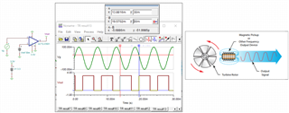
    Here is an example how Magnetic pickup signal is convert to square wave at 176.6Hz via comparator. 

    Magnetic AC to frequency Comparator 10062023.TSC

    From frequency to voltage converter, you may use LM2917. 

    https://www.ti.com/lit/ds/symlink/lm2917-n.pdf?ts=1696604938817&ref_url=https%253A%252F%252Fwww.ti.com%252Fproduct%252FLM2917-N

    https://www.ti.com/lit/an/snaa088/snaa088.pdf?ts=1696605113821&ref_url=https%253A%252F%252Fwww.google.com%252F

    https://www.ti.com/lit/ds/snosbi2c/snosbi2c.pdf

    If you need assistant, I can send a simulation for the application. 

    You mentioned that your current F-to-I convertor failed to work is likely due to sensitivity in low frequency operating range. Your maximum full flow is close to 250gpm, which is the full frequency range is operated at approx. 220.8Hz. The existing F2I converter is likely operated up to 3500Hz. So you would need to find low frequency F2I converter for the application. 

    Regarding to mikroe's evm board, it will work with some modification. I have sent you the XTR116 simulation, and you may use it as guidance for the 4-20mA V-to-I conversion.  

    If you have other questions, please let me know. 

    Best,

    Raymond