Part Number: XTR116
Other Parts Discussed in Thread: XTR106
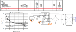
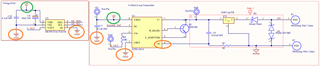
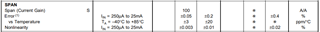
We have designed a 4-20mA product in the datasheet they have told non linearity error is 0.003% but we are getting 3% error please find attached schematics and help me out anyone find bug4-20mA Loop Transmitter sA.PDF