This thread has been locked.

If you have a related question, please click the "Ask a related question" button in the top right corner. The newly created question will be automatically linked to this question.

INA849: Reading small AC current noise

Part Number: INA849
Other Parts Discussed in Thread: INA848

Hello,

I have a current source driving a laser diode. I would like to measure the AC component of the drive current so that I can characterize the source's noise.

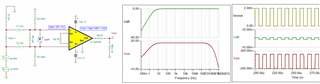
I plan to use the INA849 as shown in the image below.  I am looking for any advice (even obvious stuff) as it is the first time I'll be using this component or making a circuit like this.

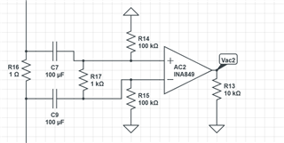
In the image, the source is above and the load follows below. The circuit is similar to what I see in another post: (https://e2e.ti.com/support/amplifiers-group/amplifiers/f/amplifiers-forum/1214506/ina849-frequency-response-and-the-connection-of-the-ref/4600177). I'd ground Vref. I plan to use low ESR SMT Tantalum caps; the capacitance C doesn't t roll off appreciably until > 100 kHz. Is it important that the 100 kOhm resistors be matched? I planned to use G=1000, as the datasheet says the BW is still 1.3 MHz there but would like some advice on the tradeoffs here, if any.

The output of this circuit (Vac2) would go to an o-scope for analysis (FFT etc...)

The DC current will be in the range of 0...500 mA.  The noise is expected to be < 1 uA. I would like to be sensitive to at least 0.1 uV. I would like to measure signals from ~few Hz to 1 MHz ideally, but can be flexible on the top end especially.  Simulating the circuit above seem to show the desired frequency response.

Thanks for any pointers.

  • Hi Adam,

    I am looking for any advice (even obvious stuff) as it is the first time I'll be using this component or making a circuit like this.

    You may try the following circuit, see the simulation file. Here are several highlights. 

    1. The input Vdiff is only interested the AC differential signals about a few Hz with HPFs (differential and common mode HPFs)

    2.  I lowered the INA849's gain to 201V/V and you should have enough signal to measure the laser diode's current noises

    3. I placed 50Ω at the output to match the scope probe's 50Ω impedance for low signal measurement (use 1X probe). Limit the scope BW to 20MHz or lower for the noise measurement. 

    4. I kept 1Ω sensing resistor. You should use low inductance <5nH Rsense, and low temperature coefficient type. The heat dissipation is approx. 0.25W at 0.5Adc current.    

    5. Use low noise linear ±12Vdc dual supply rails. Place low ESR (~10mΩ), 2.2uf -10uf  MLCC ceramic decoupling capacitors next to each of the supply rail.

    6. AC coupling 22uF and input impedance lines (including the length of the cable) to the INA840's input terminals should be impedance matched as close as possible. 

    7.  200kΩ resistors does not have to be well matched, but use 1% or better tolerance should do. 

    8.  If you have to use 1000V/V in INA849, you may try INA848 and reduce Rsense from 1Ω to lower the figure. INA848 has a fixed gain IA at 2000V/V (I do not have information about the laser the modulated frequency signals). 

    https://www.ti.com/lit/ds/symlink/ina848.pdf?ts=1696352746308&ref_url=https%253A%252F%252Fwww.google.com%252F

    9. Please consider the high side Rsense vs. Low side Rsense, since the current noise interest if the laser as load and Laser driver. You may need to pay attention to Vcm of the input signals across the Rsense, since I do not know how the laser load is configured. 

    INA849 Isen Laser 10032023.TSC

    If you have other questions, please let us know. 

    Best,

    Raymond

  • Thank you Raymond, that was very helpful! I have one followup question for now.

    Why lower the gain? Is  it just to keep the higher bandwidth, or are there other reason to keep it low? From the datasheet it looked like noise and CMRR are all better at the higher gains.

    Best Regards,

    Adam

  • Hi Adam,

    Why lower the gain? Is  it just to keep the higher bandwidth, or are there other reason to keep it low?

    Every configuration has pros and cons effects for a design requirements. 

    From the captured image below, CMRR and PSRR will improve as IA's gain are increased, which are good things. However the %gain_error and other effect may start to become critical. For instance, at 1000V/V, the Rg gain resistor (~6Ω) matching and input Rg's parasitics at the input pins are become critical in layout and IA stability may affect the performance over wide range of operating parameters. So I kept the gains low for this reasons. I recommended to keep the power rails with lower ripple and lower noises for the IA, and therefore the benefits of the higher CMRR and PSRR dBs are not as important in your system configuration anymore. 


    BTW, you should read the fine prints under each table in a datasheet and figure plots. These provide a better indicator over a wider temperature range. 

    INA848 will be better for higher and fixed gain configuration, since Rg is internal to the IA and resistor matchings are optimized. These related %errors are still there, but it is minimized in the integrated IC design. The higher gains reduces the BW, but it still has BW up to 2.8MHz. 

    Anyway, these are design trade off in the IA selections, and it depends on the application's design requirements, which ones are more important among a list of the influence variables.

    If you have other questions, please let us know. 

    Best,

    Raymond