This thread has been locked.
If you have a related question, please click the "Ask a related question" button in the top right corner. The newly created question will be automatically linked to this question.
Hello!
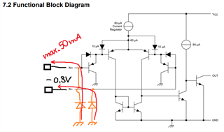
Can you elaborate on the spec "Current into input pins (IN+, IN-)"?
(Chapter 6.1 Absolute Maximum Ratings; table line 4)
To my understanding the inputs of the comparator are of high input resistance. The spec in mA range is quite confusing to me.
The maximum spec is -50mA. Is this the maximum current that can be forced into the inputs of the device at worst-case conditions? (e.g. very high temp)
Please let me know what is behind the thought process of specifying this in the datasheet and in what cases it could get important to the design.
Thank you very much!
There are clamping diodes from GND; a large current can flow only if the input voltage is below −0.3 V.
If the input voltage is below −0.3 V and the current is limited to less than 50 mA, the device will not be damaged (but will not work correctly).
Did I understand this correctly?
The clamping diodes to GND create allow for current flow in case the input's are at ~ -0.3V.
As long as the current flowing through these diodes is below 50mA the device will work properly and does not get damaged.
Is an external current limit to this 50mA reverse current out of the input suggested if the design can go into the -0.3V case for Vin +-?
No, when a current flows through these diodes, the comparator will not work correctly.
If negative voltages can happen, you indeed need a current limit. A series resistor is the simplest solution, but additional components like diodes or TVS diodes are also commonly used.
Hello Mitchel,
Please see section 2.9 of the LM339 family appnote:
Application Design Guidelines for LM339, LM393, TL331 Family Comparators
As Clemens says, the 50mA limit is for the reversed body diode to GND. Above GND the current will be the -3nA bias current up to the VCM limit, where it will then go to pA's as the input stage gets cut off (see section 2.5 of the appnote).
Thank you for the explanation - this is clear to me now on the current path.
What I am still uncertain about is if the reverse body diodes are already integrated in the device or need to be added externally just as in the app note.
The substrate diodes are part of the die.
It is possible to add more robust external diodes in order to prevent the internal ones from burning out.