This thread has been locked.

If you have a related question, please click the "Ask a related question" button in the top right corner. The newly created question will be automatically linked to this question.

LM324: Can I use LM324 to form an instrumentation amplifier

Part Number: LM324
Other Parts Discussed in Thread: LMV324A, INA350, , , TLV9001, TLV9301, INA597

Hi There,

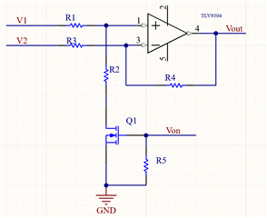
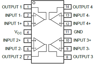
To design a relatively high precision amplifier and with low cost, I would like to use LM324 form an instrumentation amplifier. The schematic is as blew:

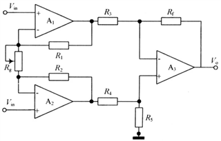
If all the resistors here have 0.5% tolerance, what accuracy of the amplifier can I expect?

Regards

Alex Chen

  • The worst error happens when A1 has a negative offset (−7 mV) and A2,A3 have a positive offset (7 mV), and when R3,R4 are too small and R1,R2,R5,Rf are too large.

    With all resistors 10 kΩ ± 50 Ω, and Rg = 2222 Ω for G=10, a differential input of 0 V results in an output of 0.156 V, and 1 V results in 10.302 V. (And I have ignored the effects of common-mode rejection.)

    You should replace the LM324 with a better and cheaper device like the LM324B, or LM324LV/LMV324A at low voltages. Also consider an integrated instrumentation amplifier like the INA350.

  • Thank you for the recommendation of LM324B which has smaller offset. I have further questions:

    1. If I do calibration at input of 0V, can I get better accuracy?

    2. My use case is G=0.5. I use it to measure the voltage of No.3 cell in a 4-serie lithium-ion battery pack. As the power of MCU is 3.3V, I would like the highest voltage to be no more than 2.5V, then ADC can read it well. In the case of G=0.5, can it be more accurate?

    3. If I don't use instrumentation amplifier, are there any other types of circuits which provide higher accuracy?

    Regards

    Alex Chen

  • 1. Yes, but calibration at a single point will not be very helpful.

    2. Yes; the input offset voltage is multiplied by the gain. But there are other errors.

    3. A differential amplifier use a single opamp (remove A1,A2 and R1,R2,Rg). This will load the battery, but you can use high-valued resistors if you use a CMOS opamp with low input bias currents, e.g., TLV9001 or TLV9301.

    To find out the properties of your intended circuits, use a circuit simulator.

  • Thanks Clemens for your information. I am going to take your recommendation. I got some questions.

    1. At how many points should I do calibration?

    2. I made a schematic as below.


    For power saving, I add Q1 to turn on/off bias. Does this circuit work?

    Regards

    Alex Chen

  • 1. Assuming linear errors, two points. But there are also CMRR effects, and the circuit it not able to measure the common-mode voltage, so you will not be able to compensate for that. With discrete resistors, you will still have large errors, and I doubt that the lower cost compared to an integrated difference amplifier like the INA597 would be worth it.

    2. This circuit will work to disconnect the V1 input from ground.

  • But INA597 is over-specification. If I employ LM324B, can I choose a pair of OP to counterbalance the offset?

    Like using OP1 and OP4 as a pair or using OP1 and OP2 as a pair.

    Regards

    Alex Chen

  • The offset voltages of the four amplifiers in a package do not have any relationship with each other. Using two opamps can make the offset worse.

    Your goals "high precision" and "low cost" contradict each other. You have to balance then, and choose a compromise.