This thread has been locked.

If you have a related question, please click the "Ask a related question" button in the top right corner. The newly created question will be automatically linked to this question.

OPA192: Opamp configuration

Part Number: OPA192
Other Parts Discussed in Thread: OPA2192, INA296A

Hi,

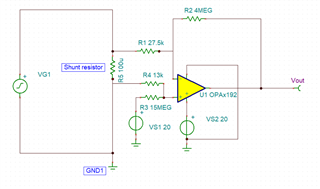
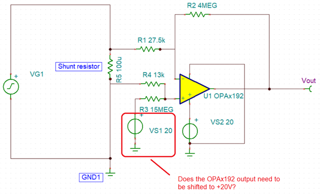
I am using an op-amp configuration as shown in the attached image for converting 0.01V pk-pk sine waveform (ac output current of the inverter, around 100A pk-pk, derived from the shunt resistor) to a level shifted and amplified sine waveform with around 1.5V peak i.e. 1V as minima and 4V as maxima to be utilized for the AIN pin of the driver IC UCC21755 (AIN pin can only sense voltages between 0.5V to 4.5V) for further sensing. Can you give your opinion on the circuit (which I simulated on TINA software, and seems to be working fine there) or issues I could face with it. One issue I can think is at 1A of output of the inverter, as the voltage across the shunt resistor is very low, the resulting output of the opamp might not be accurate. Other issue I see on TINA simulation platform is that if I do not connect GND 1 as shown in image, I do not get the desired output. Is the grounding issue a limitation of TINA or is the current sensing of the output of the inverter not possible as there is no ground element to be connected on either end of the shunt resistor.

  • HI Shishir,

    The difference amplifier as shown on the schematic above is referred to +20 V, which will attempt to shift the OPAx192 signal to +20V. This is an issue and will place the op-amp output in the rail.  Also, the UCC21755 AIN AIN voltage input range is from 0.6 V to 4.5 V, hence, the reference voltage of the OPAx192 difference amplifier is not set properly.

    - Please clarify, what is the expected DC common-mode voltage level of the shunt resistor, (the DC level of the 0.01V pk-pk AC signal) with respect to the OPA192 amplifier GND? Is this shunt resistor referred to GND as show on the simulation schematic above or is this a high-side sense solution at a higher DC common-mode voltage?

    - You have mentioned that you require an output signal of 1.5Vpk, with 1V as minima and 4V as maxima, therefore you require a gain of 150V/V. Is this correct?  What is the maximum frequency of the AC signal? 

    Thank you and Regards,

    Luis

  • Hi,

    Yes you are correct, the opamp is referred to +20V to reduce the complexity ( I am only using one +20V supply to power the auxiliary side of the inverter, and using the same supply as reference as well as the Vcc supply to the opamp). However, I am able to reduce the waveform output between +1V and +4V using the mentioned values of passives. Is that an issue?

    The dc level of the 0.01V pk-pk ac signal would be +/-0.01V maximum for my application. No, the shunt resistor is not connected to ground. In the inverter, the shunt resistor is placed between the output of the inverter and input of the motor.So, considering that, shunt resistor would always be subjected to maximum of 100V dc common mode voltage, when the inverter is functioning. That is what I am worried about as the simulation does not seem to work if I do not connect ground to the VG1 supply. But I did not give it much thought as I have faced the same issue several times in different analog circuit simulations using TiNA software.

    Yes, I require a gain of 150V/V. The maximum frequency (fundamental) of the ac signal is 50Hz. 

  • HI Shishir, 

    As you have mention, the main challenge is the input DC common-mode voltage level of the shunt resistor at 100V DC. The OPA192 difference amplifier, powered with a +20V supply, configured on a gain configuration will not be able to accommodate the +100V DC large input common-mode voltage, as the device will see input voltages exceeding the op-amp supply at the amplifier inputs. 

    Regarding the reference voltage of the difference amplifier, this needs to be set at VREF=+2.5V to center the 1.5Vpeak output signal, so you obtain +1V minima and 4V maxima.

    Below is a good application note that discusses the difference amplifier in detail:

     Difference Amplifier (Subtractor) Circuit

    In order to accept the +100V DC common-mode voltage, below is one possible circuit using the INA296A5 current sense amplifier, and the dual OPA2192 op-amp. 

    The INA296A5 offers a gain of 200V/V, and the device is able to accept bidirectional input signals up to +110V DC input common-mode voltage while powered with a +20V supply.  Assuming the +100V DC voltage is positive, this device will work.   (There are different variants of the INA296Ax depending on the voltage gain required.)

    Since the input signal is 0.010V pk-pk, and you require a 3V pk-pk (1.5Vpk) output, the required circuit gain is 300V/V. Therefore, I followed the INA296A5 (G=200V/V) with a OPAx192 non-inverting amplifier circuit set on a gain of +1.5-V/V for an overall circuit gain of 300V/V.  

    Edit: 10/11/2023, replaced difference amplifier with non-inverting configuration.

    The output 1.5Vpk signal needs to be centered at 2.5V. To generate the reference voltage, I used a voltage divider an a second op-amp of the dual OPA2192 to generate the 2.5V reference voltage.  Alternatively, you could choose a 2.5V precision voltage reference device that can be powered by the 20V supply.

    Please see one possible circuit below and transient simulation result. 

    TINA simulation file:

    FORUM_INA296A4_OPA192_non-inverting_amp.TSC

    I am part of the Precision Amplifier teams, and I am happy to support the OPAx192 questions.

    If you have detailed questions regarding the INA296A current sense amplifier, I can refer your query to the current sense amplifier applications team that will be able to support the INA296A device or be able to offer other current sense amplifier solutions.

    Thank you and Regards,

    Luis 


  • Hi Luis,

    Thank you for your detailed explanation. I am sure this will help me to achieve accurate sensing of the ac currents.

  • Hi Shishir,

    Thank you.  The INA296A4 will work as long as the DC common-mode voltage is within the range of -5V to +110V.

    The 2.5V reference accuracy is a direct function of the +20V supply accuracy/stability, and the resistor divider tolerance.  If you foresee to require a higher precision 2.5V reference due to voltage supply variation, you can always replace this voltage divider circuit, with a dedicated precision 2.5V reference device. 

    Thank you and Kind Regards,

    Luis