This thread has been locked.

If you have a related question, please click the "Ask a related question" button in the top right corner. The newly created question will be automatically linked to this question.

LM8272: LTspice model - Intrinsic Noise analysis confirmation

Part Number: LM8272
Other Parts Discussed in Thread: OPA2991

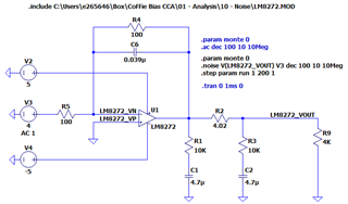
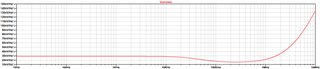
I would like to confirm the LM8272 LTspice model intrinsic noise analysis below. It looks like the intrinsic noise output after 1MHz is unbounded.

Could you confirm the behavior from Figure 2?

Figure 1 - Circuit

Figure 2 - Noise analysis with no capacitor output

  • Hey Esteban, 

    Welcome to e2e! 
    The LM8272 is a legacy device made by National in 2000, as was the model. From what I can tell in the .MOD file noise is not covered: 

    However, the noise can be calculated, we have a TI Precision Labs training series that covers the steps to calculation: Link

    I recommend watching "Simplifying calculations" 

    ...

    If you desire to instead simulate, I recommend upgrading the device to one which noise is included in the simulation file. 

    Depending on your circuit's input frequency range and voltage range and expected output, I can make a more informed suggestion. Looking at what is currently provided, I would start with OPA2991. 

    All the best,
    Carolina 

  • Thanks Carolina for verifying that the LM8272 does not include the noise model and for the reference videos on how to create your own noise model.

    There is one more think I would like to clarify. Form my previous post, it looks like the noise plot from LTspice didn't make it through. Below is the noise plot from LTspice. I know that this model does not provide the correct 1/f and white noise levels but could you verify that the behavior from 1MHz - 10MHz from the noise plot below is correct or in-correct? I am working a very low noise application that assume a significant noise roll of at 100KHz. I have noticed that if I add a 0.1uf or 0.01uF capacitor at the output it damps that behavior significantly. I just want to make sure I know what's going on at those frequencies so I can design accordingly. 

    Unfortunately, I don't have TINA installed in my machine and it will probably take me a couple of day to get it. If you can, could you verify this circuit using the TINA software in you end?

    Go Gators :)

  • Hey Esteban, 

    Go Gators! 

    The video I linked helps quickly calculate your noise so you may know the dominant noise source. 
    You may continue to use LTSpice if you wish, the models from ti.com can be 3rd party imported.
    LTSpice is a ADI simulator so we do not support it. 

    It makes sense that when CF is implemented at high frequencies the output noise is reduced.
    This is because at high frequencies the feedback capacitor becomes a "short" which in turn makes the gain = 1. 

    Here is a snippet of the next video in that series: "Noise spice simulation"

    Here is also a snippet from the analog engineer's pocket reference guide:

    As you change the external load capacitors this will also change the noise response: 

    TI also has a filter design tool: https://webench.ti.com/filter-design-tool/

    All the best,
    Carolina

  • Thanks! After analyzing the LM8272 model, I think the model is not accurately depicting the noise behavior from 1MHz - 10MHz. 

  • Hey Esteban, 

    I agree, any other TI HV op amps that you might have on your AVL? 

    All the best,
    Carolina

  • Not at this moment. The LM8272 component has already been chosen for the design but I'll be using the reference videos to build a noise model. 

  • Understood, thank you for posting on e2e :)