This thread has been locked.

If you have a related question, please click the "Ask a related question" button in the top right corner. The newly created question will be automatically linked to this question.

LF398-N: Amplifiers forum

Part Number: LF398-N

Hi Team,

I have AD582 in my board. I want to replace it with LF398-N. Pls let me know how to modify the LOGIC and LOGIC REFERENCE signals connection.

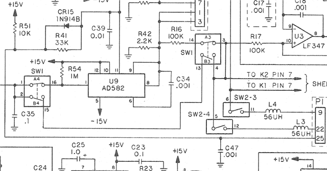
Existing circuit with AD582 is shown below.

Regards,

Srikanth Kacchu

  • Hi Team,

    I confused to interpret Figure 18 & 19 from datasheet of LF398-N. How to switch the device to Sample and Hold Modes?

    Regards,

    Srikanth Kacchu

  • Hi Srikanth,

    Pin 7 is the logic reference pin while pin 8 is the logic input pin. The sample function will trigger when Pin 8 is ~2.4V higher than pin 7. The hold function will trigger when the pin 8 is less than ~0.8V higher than pin 7.

    Figure 18 shows how the device can be configured to trigger a sample on logic high. Figure 19 shows how the device can be configured to sample on logic low.

    For some reason I am unable to view the existing schematic, can you try uploading the image again? You may simply copy and paste a screen show into your reply. Or you may drag a .pdf file directly into the reply.

    What is your logic high voltage? What is your logic low voltage? Do you want to sample on logic high and hold on logic low? Or do you want to sample on logic low and hold on logic high?

    Regards,

    Zach

  • Hi Zach,

            What will happen when difference between logic and logic reference is 0.8V to 2.4V. In what mode it will exist in between that range whether in sample mode or hold mode. Kindly confirm.

    Regards,

    Pradeepraj M

  • Hi Zach

    Thanks for your feedback. Pls find the attached schematic with AD582.

    Regards,

    Srikanth Kacchu

  • Hi Zach,

    What is the significance of Threshold = 1.4V?

    Regards,

    Srikanth Kacchu

  • Hi Zach

    Below highlighted sentence is not clear. Could you please rephrase?

    Regards

    Srikanth Kacchu

  • Hi Srikanth,

    What will happen when difference between logic and logic reference is 0.8V to 2.4V. In what mode it will exist in between that range whether in sample mode or hold mode.

    The range between 0.8V and 2.4V is not a valid logic input to the device. The difference between logic and logic reference must always put the device into a logic HIGH or logic LOW state. If the device is not in a valid logic high or logic low state, we cannot predict if the device is in sample mode or hold mode.

    What is the significance of Threshold = 1.4V?

    1.4V is the typical logic threshold value. The exact threshold voltage will vary between individual devices and therefore the minimum and maximum threshold voltage must also be considered. The logic high input must always exceed the maximum threshold (2.4V) and the logic low input must always be less than the minimum threshold (0.8V).

    Below highlighted sentence is not clear. Could you please rephrase?

    The hold function will trigger when the differential logic voltage (pin 8 - pin 7) is less than 0.8V.

    Note that these are the minimum and maximum threshold voltages for the device to recognize a valid logic signal. Consider the case where pin 7 (logic reference) is connected to the digital ground at 0V. A typical logic input to the pin 8 of the device will be something like 0V for logic low and 5V (or 3.3V) for logic high.

    In this case, 0V is a valid logic low input (0V < 0.8V) and 5V is a valid logic high input (5V > 2.4V).

    3.3V is also a valid logic high input (3.3V > 2.4V).

    Regards,

    Zach

  • Hi Zack,

         We are going to replace AD582KD with LF398-n. While validating AD582KD in bench level testing.

    The tested scenario and the observations are attached below,


                   Inputs Given: +Vs = 15V, -Vs = -15V, +Logic = +15V.


                   Results:

    Details mentioned in datasheet

    Calculated / Actual value

    Measured Value

    Hold Mode

    > 13 V

    >11.6 V

    Sample Mode

    < 14.2 V

    <11.6 V


                   Schematic diagram attached above. Kindly confirm why there is difference with refer to datasheet.

                   *Low-Cost Sample-and-Hold Amplifier Data Sheet (Rev. A) (analog.com)

    Regards,

    Pradeepraj M

  • Hi Pradeepraj,

    I can support any questions you have regarding the LF398-N or other Texas Instruments devices. The AD582 is not a TI device and therefore I cannot comment on the device datasheet or any discrepancies you see in your bench level testing.

    Regards,

    Zach