This thread has been locked.

If you have a related question, please click the "Ask a related question" button in the top right corner. The newly created question will be automatically linked to this question.

OPA2188: Rail to Rail Output

Part Number: OPA2188
Other Parts Discussed in Thread: OPA188

I have a question about Rail to Rail.

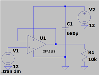
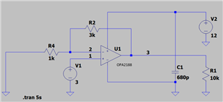
Perform the setup as shown in the figure.

Power supply voltage: 12V , Non-inverting input terminals: 3V

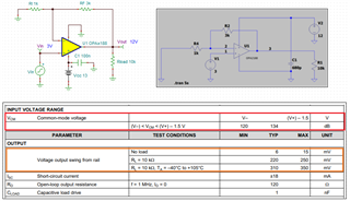
Measurement results:① Non-inverting input terminals: 2.990V , ② Inverting input terminal: 2.860V , ③ Output: 11.493V

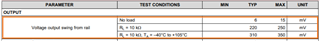
Since the data sheet said Rail to Rail Output, I thought that the output was 12V, but why was it as low as 0.507V?

What is the difference between Rail to Rail Output , Rail to Rail Input and Rail to Rail Input & Output?

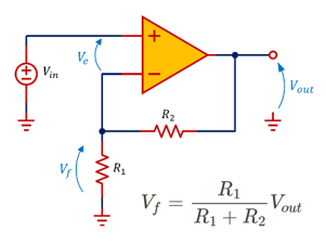
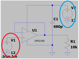
When set up in the form of a voltage follower, the output was 11.224V against the input of 12V.

Why was the output so low even with the Voltage Follower?

  • This device does not have rail-to-rail inputs, i.e., the common-mode input voltage range goes only up to V+ − 1.5 V. Your circuit must not try to apply higher voltages at the inputs.

  • Hi Kenta,

    What is the difference between Rail to Rail Output , Rail to Rail Input and Rail to Rail Input & Output?

    As Clemens replied, the OPA188/OPA2188 is considered as Rail to Rail (RRO) op amp, but no op amps are output will be able to output a voltage all the way up to the supply rail.  With Vin = 3Vdc, Gain = 4, Vout = 12Vdc, the output voltage will reach close to to the rail. In this case, the Vout may hit close to 11.5V out of 12V supply rail over temperature, see the datasheet below. You may also consider to increase the output margins somewhat, due to the differences of your use conditions vs. the test conditions specified in the datasheet. 

    OPA188 RRO 11132023.TSC

    Since Vout is required to be measured at 12Vdc and input is configured at 3V, one of the option is to increase the voltage supply rail, say 13Vdc to 15Vdc. 

    Why was the output so low even with the Voltage Follower?

    In a voltage follower configuration in the OPA2188, the common mode input is ranged up to V+ - 1.5 V , as shown in the datasheet above. The Vin = 12V in OPA2188 violates the Vcm monde range, which the output is no longer linear w.r.t. the input.

    If you have other questions, please let us know. 

    Best,

    Raymond   

  • Thank you for your answer.

    I understand that Rail to Rail Output can output up to the power supply voltage, but was that wrong?

    How can you output 12Vdc other than increasing the power supply?

  • Hi Kenta,

    Per OPA188's datasheet, Vin = 3Vdc, Gains = 4 V/V as simulated, which it meets the Vcm input voltage requirements. The output voltage is 12Vdc as simulated and V+ is 13Vdc, and Vout is approx. 1V from V+ supply.  Per the Vout range with 10kΩ load, the Vout voltage swing is within the specified rail, which is 13 Vdc.

    I understand that Rail to Rail Output can output up to the power supply voltage, but was that wrong?

    Every op amp's output voltage swing ranges are slightly different, so you have to check out the OPA188's datasheet and the specification. At room temperature under no load condition, OPA188's Vout is very close to the supply rail. 

    If you have other questions, please let us know. 

    Best,

    RAymond 

  • Hi Raymond,

    Raymond said: Per OPA188's datasheet, Vin = 3Vdc, Gains = 4 V/V as simulated, which it meets the Vcm input voltage requirements.

    Why does it meet the Vcm input voltage requirements?

    I'm having trouble figuring out how to calculate.

    In the figure above, Vf=1k/(1k+3k)*12=3 (V)

    Isn't the V+ of the common-mode input voltage range 10.5 VDC, which is 1.5 V lower than the 12 VDC?

  • Hi Kenta,

    Vcm refers to the input voltage range. For V+ = 13 Vdc as simulated, the input range is from V- (GND or 0V) to (13V - 1.5V) = 11.5V for OPA188. We also indicate that the OPA188 is NOT Rail to Rail Input (RRI) op amp. 

    But OPA188 is classified as RRO output, where the Vout does go near to the V+ rail (depending on load). For V+ = 13Vdc, the output may go up to 12.5Vdc. 

    You submitted 2 inquiries. The 1st circuit has gains of 4V/V and 2nd circuit has gain of 1V/V.  

    The image below is the first circuit in your inquiry, where Vin =3V=Vf as you show, and Vout = 12Vdc as calculated and simulated. In non-inverting configuration, the gains is (1+ R2/R1), which you shown correctly in the image below. 

    Under the linear operating mode, Vin should equal to Vf as shown in the image below, and Ve should be close to 0V or very very small in real world test conditions. In other words, Vin = Vf when the op amp is operating in linear mode.  

    In the 2nd inquiry, your Vin = 12Vdc, which is circled in red. V+ = V2 = 12Vdc (V+ here refers to Vcc or the supply voltage of the op amp), and the Vcm mode or the input voltage exceeds 12V - 1.5V = 10.5V. Therefore, the input Vin = V1 violates the input Vcm range as presented in the OPA188's datasheet (V1 > 10.5V). When the input is placed outside of Vcm range, the op amp is no longer operating linearly.

    The output voltage of 11.224V in OPA188 per your 2nd inquiry is operated in saturation and railed to the supply voltage. 11.224V has no meaning, since the op amp is NOT operating in a linear mode. The 11.224V is likely the saturation voltage for OPA188 with V+ supply rail configured at 12Vdc. 

    If you have other questions, please let us know. Please close the inquiry if your issues are resolved. 

    Best,

    Raymond