This thread has been locked.

If you have a related question, please click the "Ask a related question" button in the top right corner. The newly created question will be automatically linked to this question.

INA300-Q1: Understanding Vsense_min Calculation in Relation to Load Current Sensing

Part Number: INA300-Q1
Other Parts Discussed in Thread: INA300

Hi Team,

I'm utilizing the INA300-Q1 in my design for overcurrent protection, and the schematic is provided for your reference.


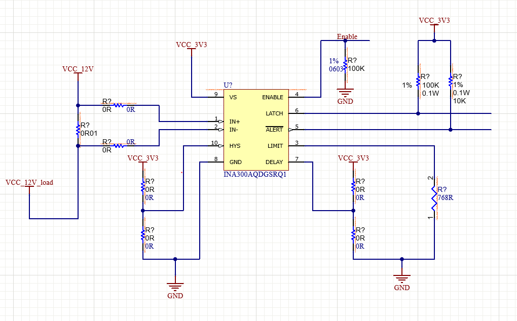
The design is intended for two different loads:

1. 12V@1.5A max (as depicted in the above schematic)
2. 15V@500mA max

The VCC_12V or VCC_15V is supplied by a 2A DC-DC converter. My approach is to use the sense resistor for 2A support and control the load current limit by choosing the appropriate limit resistor.

I've selected a current sense resistor of 10mOhm, and here are the calculations for finding the Limit Threshold Setting Resistor, RLIMIT:

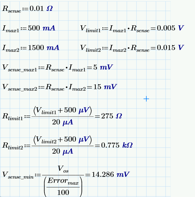
1. I'm a bit confused with the Vsense_min value calculation. According to the datasheet, Vsense_min is calculated as shown above, considering a 3.5% Errormax. Could you please explain the significance of this value? My calculations indicate that the Vsense_max for a 500mA current is 5mV, which is less than Vsense_min. Does this mean the INA300-Q1 might struggle to sense the load current?

2. Kindly review the schematic and let me know if any modifications are required to align with my requirements.

--

Thanks in Advance

Kiran

  • Hi Kiran,

    I assume you followed the design procedure in the data sheet. In that example, the 3.5% number is the error budget assigned to INA300.

    1. In your calculation, Vsense_max is 5mV, which is less than Vsense_min. This means the % error will be greater than 3.5%, or about 10%. In other words, the current design is not capable of supporting 3.5% error.
    2. An option is to increase the shunt resistor, which increases the shunt voltage and consequently pushes down the % error. An acceptable shunt resistor value can be found by a few iterations, but 30mOhm or larger should be OK from accuracy perspective.

    Regards, Guang

  • Hi Guang,

    Thanks for the  response.

    For the load currents of 500mA and 1.5A, I've considered the values of 50mOhm and 25mOhm, respectively.

    Regarding the input filtering, I've used the equation provided in the EVM user guide to calculate the value of C. However, I'm curious about the factors that should be considered in determining the cutoff frequency. Could you please provide guidance on this?

    --

    Thanks in Advance, 

    Kiran 

  • Hi Kiran,

    The filter is to prevent high frequency noise on the input from being coupled to the output. Whether the noise comes from a switching power supply or is being introduced during EMI testing, the cutoff frequency can be chosen to help filter out the noise.

    If not sure, a place holder can be reserved on the PCB. A filter can be fitted later on during verification stage if it turns out one is needed.

    Regards, Guang

  • Hi Guang,

    I have doubt regarding a INA300-Q1 implementation.  Instead of using LATCH signal to unlatch the ALERT output, can we toggle the enable signal. how does the ALERT signal behaves when the ENABLE is pulled low and high?  My concern is to use only one signal i.e., enable for both enabling/disabling the INA and to unlatch the ALERT output. How does the INA behaves in such conditions? 

    --

    Thanks in Advance,

    Kiran

  • Hi Kiran,

    Through Enable pin, it takes 20uS to disable the INA300; and 300uS to enable. In other words, the response of the ALERT pin might be slower from the perspective of Enable pin. Here is a typical response curve.

    There shouldn’t be glitches if that is what you worry about.

    Regards, Guang