This thread has been locked.

If you have a related question, please click the "Ask a related question" button in the top right corner. The newly created question will be automatically linked to this question.

LMH32404RHFEVM: Balun connection on the LMH32404 EVB

Part Number: LMH32404RHFEVM
Other Parts Discussed in Thread: LMH32404

Hello,

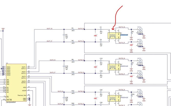
I looked into the schematic of the LMH32404RHFEVM.

Is there any chance that the output baluns (transformers from Coilcraft : JA4220-ALB have been connected in the wrong way?

This transformer pinout is actually as in Coilcraft datasheet:

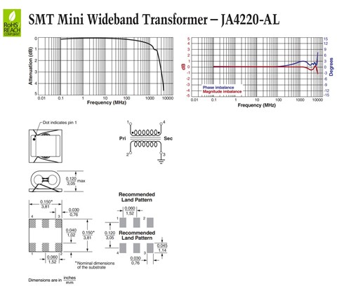
Therefore the differential lines should have been connected to pins #2 and #3 of the transformer while the single-ended output should have been taken from pin #1 or #4, while the other one is grounded.

Am I right, or I missed something?

Thanks

Sariel

  • Hello Sariel,

    Good question!  Baluns & transformers can be confusing, especially when deciphering a schematic from another person or company.  While intuition may suggest that baluns should always be wired up with a 'vertical' orientation (see Voltage Balun in Figure 3 of linked article), there are cases such as the LMH32404RHFEVM where the 'horizontal' orientation used does make sense for the circuit application.

    As the signaling needs require a transformation from differential to single-ended signal (or balanced to unbalanced), the transformer is placed in-line to the differential output signals.  This may appear counter-intuitive, as there would "appear" to be a "short" of the output signals directly to the SMA connectors.  However, what is actually happening is this: the transformer (balun) is being used in a current balun configuration.  You can read a bit about current baluns in the article below; I will leave it to you to explore the theory in detail.

    Essentially the current-balun configuration is most appropriate for the LMH32404RHFEVM; the impedance matching is handled by selected resistors and allow for a differential to single-ended conversion for the OUT+ SMA connector.  If differential output signaling is desired, the transformers T1, T2, T3, and/or T4 can be removed and shorted across the output lines.  Be careful to also desolder R2, R7, R16, or R27 depending on which transformers are removed.  These resistors short OUT- signals to GND.

    https://blog.minicircuits.com/demystifying-transformers-baluns-and-ununs/

    Best,

    Alec

  • Thank you for responding, Alec.

    Could you kindly share the article you mentioned in your response? It wasn't included, and I'm eager to read and learn more.

    Best regards, Sariel

  • Hello Sariel,

    The article should be linked in my above response.  I have added it here again just to make sure I do not leave it missing Slight smile.

    https://blog.minicircuits.com/demystifying-transformers-baluns-and-ununs/

    Best,

    Alec

  • Thank you once more, Alec.

    After delving further into current baluns, could you explain why the current-balun configuration is deemed most suitable for the LMH32404RHFEVM?

    Sariel

  • Hello Sariel,

    The current balun used is well-suited for high frequency operations, including RF.  The current balun is capacitively coupled, allowing for single-ended to differential or differential to single-ended conversion.  The physics and electromagnetics are touched on briefly in this document from Marki:

    balun_basics_primer.pdf

    The LMH32404 is specifically designed for LiDAR and laser-distance measuring applications.  I can check with our designer of the LMH32404RHFEVM for clarification on balun selection.

    Best,

    Alec

  • Dear Alec,

    Certainly, I'm eager to learn about the initial considerations regarding the utilization of this balun for interfacing with the LMH32404.

    If I opt for an external (wideband) voltage-type balun connected to the LMH32404RHFEVM, while bypassing the onboard mounted balun, would it affect the measured bandwidth or output noise density compared to the results obtained with the mounted balun?

    Best regards,

    Sariel

  • Hello Sariel,

    You are certainly welcome to use a voltage-type balun or transformer.  You would be looking for a 1:1 turns ratio transformer.  You could also, as you mentioned, opt to output to both OUT+ and OUT-, using an external balun or transformer.  As real transformers are non-ideal and do act as filters across frequency, you would need to examine the insertion loss and datasheet parameters for the frequency response of the transformer.

    One of my team members explores some general LMH32404 questions, including your question about transformer vs. balun use, in a related thread:

    https://e2e.ti.com/support/amplifiers-group/amplifiers/f/amplifiers-forum/1218297/lmh32404-filter-and-balun-problems-with-lmh32404

    Best,

    Alec