This thread has been locked.

If you have a related question, please click the "Ask a related question" button in the top right corner. The newly created question will be automatically linked to this question.

OPA145: Random voltage at the Input and output of OPA145 when Input pin is floating

Part Number: OPA145
Other Parts Discussed in Thread: TMUX6208, OPA140

Hi,

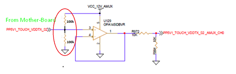
We have a circuit consisting of a OPAMP (OPA145) and AMUX (TMUX6208). The input of the OPAMP is connected to a mother-board test point. When there is no voltage from the mother board, we are getting some random voltage (from 1-3V) at the Input (pin 3) and Output (pin 1) of the OPAMP. Below is the circuit for your reference.

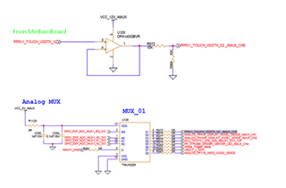
So, this random voltage might damage the mother board as this is connected to the test point of the motherboard. Also, as the same voltage is going to the AMUX, we are getting some voltages at the ADC even there is no voltage from the motherboard through the test point.

Could you please suggest some solution so that we can avoid this issue.

Thanks.

  • Since the typical input bias current (IB) polarity might be of either direction, leaving the input pin (3) floating may result in the input (and therefore output sinve Vout=Vin) being anywhere within the input common-mode or output voltage range of OPA140 - for Vs=12V single supply, 0.2V<Vout<8.5V

    In order to prevent random voltages, the best solution would be to use large resistor voltage divider to keep the input at mid-supply while floating the input - see below.

  • Hi Marek,

    Thanks for your suggestion. As the input of the Opamp is connected to the mother board test points, so I will not be able to connect any divider/pull down/pull up to that line (as per design guidelines of the mother board).

    Is there any other Opamp whose bias current is very less, so that input voltage will be very less during the floating condition? If yes, could you please suggest some part number for the same.

    Thanks.

  • The magnitude of the input bias current will only make a difference in how fast the input (and thus output) will collapse on one of its rails but it will not prevent its random voltages. The only solution for controlling the output is to control the input by any means possible like connecting the input thru a large value resistor to a desired voltage potential.  If it’s acceptable for the output to be at the ground while no input is applied from the motherboard, then you may connect the input to ground through 1M resistor, which should not effect normal operation once the input from motherboard is restored.