This thread has been locked.

If you have a related question, please click the "Ask a related question" button in the top right corner. The newly created question will be automatically linked to this question.

INA301: Hysteresis

Part Number: INA301
Other Parts Discussed in Thread: INA302, INA303, INA234, INA181

Hello,

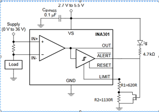
I have a question about the hysteresis of the INA301. Do to design specifications, I would like to use the A3 reference with a Vlimit of 50mV. Nevertheless, the datasheet says that it's hysteresis is 100mV, does it mean that once activated, the ALARM signal will not be deactivated again?

If so, could it be a way to  deactivate the hysteresis?
Maybe, under a minimum difference the hysteresis is not workin?

I have not see a minimum for Vlimit, but if there is no posibility for deactivate the output if the Vlimit<100mV, I consider that it should be mentioned somwhere.

Thank you in advance and best regards.

Egoitz.

  • Hello Valued Engineer,

    I am looking this over and will respond shortly.

    Sincerely,

    Peter

  • Hey Egoitz,

    There is no way to deactivate or lessen the hysteresis.

    The INA301 with a VLIMIT of 50mV is not a recommended application not only because it VLIMIT is close to they absolute hysteresis, but also because Vout at 50mV is close to the swing to ground specification of 30mV. This means that Vout from 30mV to 50mV will not be accurate of linear according to device specifications.

    This is usually not a problem because gaining Vout to a VLIMIT > 1V will benefit system signal-to-noise and accuracy performance.

    The other device options are:

    1. INA302/INA303 which include a reference pin to bias up the Vout and comparator input levels so you are not saturating Vout into ground.

    2. Digital power monitor (e.g., INA234 which an ALERT can be programmed to activate once Vin > Vlimit)

    3. Discrete INA302 solution with current-sense amplifier circuit (e.g., INA181 or INA296) and external comparator.

    Sincerely,

    Peter

  • Hi Peter,

    Thanks for your fast reply. It's a pity the hysteresis thing...nevertheless, I have new questions about:
    1. Taking into account that I will not be using the output, so that RL will be "infinite", and that I have a little marging from 30mV to 50mV, do you thing the swing could be a problem?
    2. What if I put 2 resistor for setting the Vlimit, one of them in paralell with a MOSFET commanded by the ALERT pin? When activating the ALERT signal, it will boost the limit and so, only getting down the necesary difference, it will get deactivated. Could be an option?

    With the circuit shown above (where the ALARM is connected to an opto), the VLIMIT with ALARM deactivated will be 50mV, but when it gets activated, the VLIMIT will be boosted to 140mV, so for deactivating, will be enought with getting  down the output of the amplifier from 40mV.

    Thank you and regards.

  • Hey Egoitz,

    1. Technically you would want RL (resistor at OUT pin to GND pin) to be lower than 10kΩ to get better swing to ground performance. The datasheet test this specification at 10kΩ, but you could drop that to as low as 2kΩ. As long as the effective output current is not exceeding any allowable system power dissipation from the Vs rail.

    50mV limit level is achievable, but keep in mind that the device's 6-sigma input offset (±125µV) could impose up to 5% error along on 50mV output signal.

    2. This idea is certainly a possible solution depending upon system requirements. Depending on how your are driving RESET pin, your host processor (or whatever is sensing ALERT pin) would need to be able to capture short edges. I would also try experimenting with other alternative, such as pulling LIMIT up to VS pin with a strong pull up once ALERT goes low. This way you can remove LIMIT variability from FET having to be ON during 50mV LIMIT operation.

    Sincerely,

    Peter

  • Understood, thank you for your help!

    Best regards.

    Egoitz.