- Ask a related questionWhat is a related question?A related question is a question created from another question. When the related question is created, it will be automatically linked to the original question.
This thread has been locked.
If you have a related question, please click the "Ask a related question" button in the top right corner. The newly created question will be automatically linked to this question.
Hi Team,
My customer mentioned when powered up the device looks latch-up and then the device would be broken.
Could you check the schematic?
high side sensing: common mode Voltage:5V
XX: not populated
V-:gnd
AMP_VCC:5V
Regards,
Shoo
Hi Shoo,
XX: not populated
Do you mean that the gain resistors X10, X100 and X1000 are open, where the INA333's gain is 1 V/V?

The above INA333 IA is not configured properly and the IA circuit is not operating linearly, and Vcm can not be configured in INA333 part at 5Vdc.
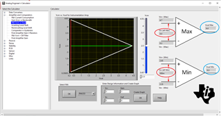
The Vcm vs. Vout is the ideal configuration for INA333, which it will be operating linearly, see the green line, which is the optimized Vcm = 2.5V point. Vcm at 5Vdc is not, shown in the upper image.

Here is an example of INA133, which is operating in linear configuration. I need your requirements in order to simulate the intended conditions. If the Vcm =5Vdc and current sensing is occurred at the high side, you may have use other IA, such INA823, INA826, perhaps INA630 (new and low cost product, but I have not seen datasheet yet).

3223.INA333 Latch up Issues 12192023.TSC
If you have other questions, please let me know.
Best,
Raymond
Hi Shoo,
I am going to close this inquiry for now. If you have other questions, please let me know.
Below is the Analog Engineer Calculator that you may use to check the linear operating point of an instrumentation amplifier.
https://www.ti.com/tool/ANALOG-ENGINEER-CALC
Best,
Raymond
Hello,
This problem also occurs at VCM=2.5V Vref=0V.
Do you have some countermeasure?
have you confirm any cases where latch-up occurs with this device?
Hi Tomomichi,
have you confirm any cases where latch-up occurs with this device?
Please define your latch-up state. Do you have to power cycle in order to restore the operation? Please provide me the complete INA333 schematic or the design requirements.
This problem also occurs at VCM=2.5V Vref=0V.
With the stated conditions, only the region inside of the triangle will behave linearly between the input Vcm signal and Vout, see the circled min and max ranges. Vout will not behave linearly outside of the triangle region, where green line is the Vcm mode condition at the input.

In order to increase the linear range, one method is to apply Vref signal. Please check it out with the mentioned tool from the previous reply. If you have other questions, please let me know.
Best,
Raymond