This thread has been locked.

If you have a related question, please click the "Ask a related question" button in the top right corner. The newly created question will be automatically linked to this question.

OPA2348-Q1: The effect of input capacitors

Part Number: OPA2348-Q1
Other Parts Discussed in Thread: OPA2348

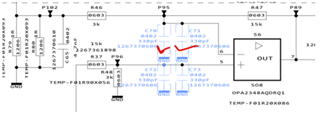
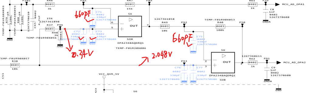
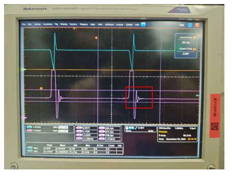
When the OPA2348 is used as a negative feedback signal amplification circuit, I added the 660pF capacitors at the "+" and " -" input to ground for improving interference resistance(shown in the picture). May I know if this can cause oscillation of the operational output signal or other negative effects? 

  • Hello Mingkang,

    660pf on the non inverting terminal “+” will not cause an issue. However, 660pF on the inverting terminal “-“ will seriously impact your stability. Here is a simulation of phase margin vs capacitance on an inverting node for a circuit with a noise gain of 1.5 on a similar op amp to OPA2348

    As you can see, after 10pF you start to lose phase margin, and it is seriously impacted after 100pF. 

    If you would like to place a filter cap to ground on the input, it should be on the other side of R36. You could also place two resistors in series, each being half the value of R36, and place double the capacitance to ground in between the two resistors. The main goal is to have some resistance between the capacitance and the inverting input 

     Best,
     Jerry

  • Thanks for your reply. We added 660pF capacitance to both the positive and negative sides of the two-stage operational amplifier. We found that only the second stage output waveform had oscillated, and the first stage output had not oscillated. Why is that? How do you evaluate how much capacitance can be added to the negative side of the load to cause the output signal to oscillate? 

  • Hi Mingkang,

    Jerry will be back next week so in the meantime I'll try to help answer. 

    I recommend taking a look at the TI Precision Labs: Op-amp Stability to better understand in more detail what causes instability, as well as how to simulate for it. 

    We found that only the second stage output waveform had oscillated, and the first stage output had not oscillated. Why is that?

    I see that the two stages have different feedback resistors. Instability is caused by having a delay between the inverting input pin and the output pin. For more details see TI Precision Labs: Op-amp Stability. When you add capacitance to the inverting input pin, you are creating an RC network with this capacitor and the feedback resistor. There's also additional capacitance not seen here, that's coming from the internal input capacitance of the op amp. 

    The second stage has a large feedback resistor making it more susceptible to causing instability when interacting with the input capacitor. 

    How do you evaluate how much capacitance can be added to the negative side of the load to cause the output signal to oscillate? 

    We run spice simulations in either TINA TI or Pspice for TI. We do a stability analysis in the circuit to determine how stable it is. We also check for 45 degrees of phase margin. I would highly recommend watching the TI Precision Labs: Op-amp Stability, as it goes into how to run simulations, and calculations. 

    Best Regards,

    Robert Clifton