Other Parts Discussed in Thread: TIDA-01471, , XTR111
------------------------------------------------------------------------------------------------------------------------------------------------------------------------------------------------------------------------
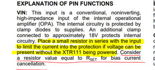
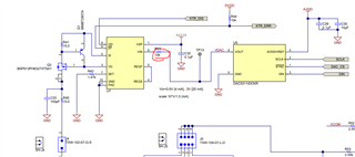
ı think its related about this section
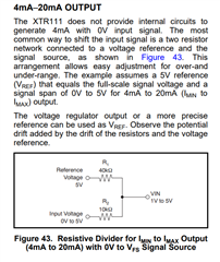
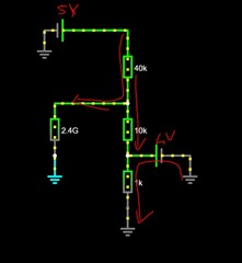
if there is no 1k ohm resistor is not connected the and Vin source lower than 5V Vin source will sinking .
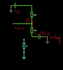
and when we add 1k res The voltage at the point we want to create will remain constant and our source will flow over 1kOhm, not sinking.
please correct me if ı wrong
--------------------------------------------------------------------------------------------------------
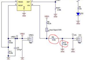
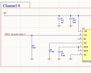
in my design (0-5 Vin 0-20mA ouput )ı have used as this (When input is floating pull down to gnd ,When the input is 5V, 5mA current is drawn, I realized that it might be better to set a higher value.)
----------------------------------------------------------------------------------------------------------------------------------------------
Likewise, we see that only 10k is used in Tida-01471. What is the purpose of this?
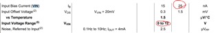
When I look at the table, I see that the bias current is quite low.