- Ask a related questionWhat is a related question?A related question is a question created from another question. When the related question is created, it will be automatically linked to the original question.
Hi,
I am doing a simulation on PGA855, and I found that the reference simulation result is not as expected.
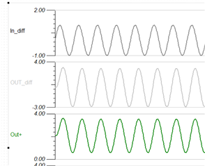
I am simulating straight from TINA reference design, where it is injecting a 1V amplitude differential signal into PGA855, with gain of 4.
But the output is only a 3V differential signal. Since this is coming from a reference simulation, I am not sure if I missed something.
And the simulation file also includes this snapshot of result: 1V amplitude In_Diff, 3V amplitude Out_diff.