Dear TI Forum Supports,
Hope you are doing well.
I'd like to get some answers from you guys about 5962-8760801GA(LF198H/883) device.
There are 2 questions below.
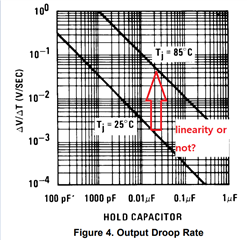
1. In datasheet of LF198, there is a graph about Output Droop Rate(See below) which has 2 lines of 25ºC and 85ºC.
I hope to get data lines between 25ºC and 85ºC, so do data lines have linearity characteristic by temperature?
If not, could I take more Output Droop Rate Data of temperature between 25ºC and 85ºC?
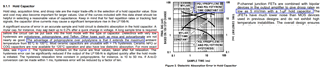
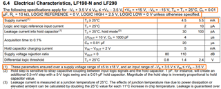
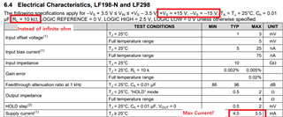
2. Coud you give me Max +Icc/-Icc(Supply current) data with +15V / -15V / RL(Load) = Infinity ohm condition?
There is only supply current under +15V / -15V / RL = 10kohm condition.
Please let me know.
Thank you in advance.
Wantae, Kim