This thread has been locked.

If you have a related question, please click the "Ask a related question" button in the top right corner. The newly created question will be automatically linked to this question.

OPA3S328: Reliable functioning of Transimpedance amplifier

Part Number: OPA3S328
Other Parts Discussed in Thread: OPA328

Hi TI

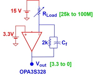
In the signal chain (PFA), we're dealing with relatively higher voltages (15 to 20 volts). We're exploring its interaction/coupling with OPA3S328 low noise amplifier where a resistive load is pulled to 15V on one side and other side is connected to the inverting terminal of the amplifier (supposedly pulled to 3.3V as per the virtual ground).

Could you provide insight into the stable/reliable functioning of this configuration? Should we consider seeking an equivalent part for this setup?

Thanks

Deep

  • Hey Deep, 

    For correct phase margin analysis, can you estimate the parasitic C at the inverting terminal - either from your Rload or wiring? 

  • Hi Michael

    Our main concern was to prevent any damage to amplifier. It will be in the range of 30-50 pF.

    Thanks

    Deep

  • Hi Deepak, 

    In the diagram above, if the input resistor on the  (IN-) inverting input terminal of the OPA3S328 is in the range of 25kΩ to 100MΩ, and the voltage at the other side of the input resistor is +15V to +20V, no damage will occur.  The 25k resistor will limit the current on the input terminal to less than 20V/25kΩ <= 0.8mA,

    On a fault, the device can withstand an input current up to ±10mA at the input current the input terminals; therefore, the device will not be damaged with +20V connected through a 25KΩ resistor. Please refer to the Absolute Maximum Ratings table on page 5 of the datasheet:

    If you would like us to review the schematic or provide further suggestions, please provide a complete schematic showing the switches of the OPA3S328, supply connections, the input resistors switched, as well as the load or circuit connected to the OPA3S328 output.

    Thank you and Regards,

    Luis

  • Thanks Deep, 

    Targeting a butterworth response the 30pF requires 12pF for Cf and the 50pF source requires 15pF where there you would be getting  9.4MHz F-3dB. 

    Setting a fixed 15pf Cf and going back down to the 30pF source, will yield and overcompensated 6.3MHz F-3dB. This is using a 40MHz GBP and 6pF added input C for the amplifier. I was using the OPA328 model info, that Aol phase looks pretty weird in the model so this might not match exactly in sim. here is that sim, the phase should be heading down from -90 towards -180deg but does not, 

    the data sheet shows this for the OPA3s328 - the phase axis is labelled wrong but the shape is right. 

  • Hi Deepak,

    Please let us know if you have additional questions.

    Thank you and Regards,

    Luis


  • Hi Luis

    I do not have more questions as of now.

    Thanks

    Deep