This thread has been locked.

If you have a related question, please click the "Ask a related question" button in the top right corner. The newly created question will be automatically linked to this question.

TLV314-Q1: generating offset for ADC reading

Part Number: TLV314-Q1
Other Parts Discussed in Thread: TLV314

Hello,

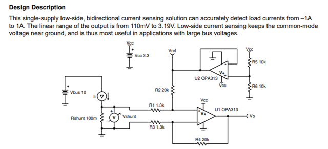
To read the current of each phase in motor drive application, shown in figure 1 (Ia, Ib, Ic), an offset voltage of 1.65V is created using TLV314.This is due to the fact that the current is bidirectional and ADC can only read values between 0 and 3.3V.

My question is : can I use only one reference voltage TLV314 for three shunt measurements or I should use three separate TLV314? 

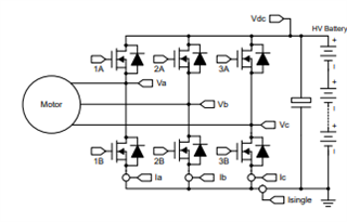
Figure 1. motor drive circuit

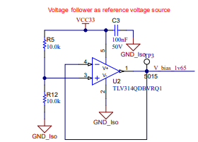
Figure 2. offset voltage generator circuit

Regards,

Hadi

  • Hey Hadi, 

    It is acceptable to use one voltage follower as a single reference voltage source for the three terminals if the current sense solution follows the concept in this figure:

    https://www.ti.com/lit/an/sboa223b/sboa223b.pdf

    More details on the this single-supply low-side, bidirectional current sensing solution can be found in this link. 

    Regards,

    Ore. 

  • Hey Ore,

    Thanks for your reply.

    The only concept in the figure is the common mode voltage.

    So, you think that we can use a voltage follower as a reference voltage even for 10 circuits if the common-mode voltage is near ground? How about the maximum load capacitance and minimum load resistance  that op-amp can supply?

    Regards,

    Hadi

  • Hey Hadi, 

    If you go through the .pdf, you would see it is describing a current sensing solution with the use of a Vref generated from a buffer biasing the differential op-amp configuration that would be amplifying the Vshunt. In your case, VshuntA,VshuntB,VshuntC, correct? Please correct me if I am wrong.

    And to answer if you can use one reference buffer for up to 10 circuits. It depends. The buffer circuit can drive a 1nF cap load and still be stable. 

    And if the buffer output is connected to the non-inverting input with a capacitance of ~5pF 

    theoretically,10 op-amps connected as the cap load would look like a 50pF cap load to the buffer and should be fine. But for best practices an isolating resistor(in this case R2 from the figure) between the reference buffer output and any cap load is advisable. And the current sensing solution attached to this thread shows the buffer is isolated.

    I would like to point out for this application. The vref is at mid supply and so is the common mode. The power supply is on a single supply and not split supply rail. 

    As for the minimum load resistance. Figure 7 from the datasheet shows how different loads can affect the output swing. At 10kOhms, the output swings 5mV from the rails. 


    I hope this answered your question? If not feel free to clarify. 

    Regards,

    Ore.

  • Thanks Ore for your detailed answer.

    Regards,

    Hadi