This thread has been locked.
If you have a related question, please click the "Ask a related question" button in the top right corner. The newly created question will be automatically linked to this question.
Hello,
I using INA193 to measure current from isloated power line.
INA193 is connected to 5V in V+ pin, GND to V-.
Vin + and Vin - are connected with 20m oHm resistor, the ground reference of Vin + and Vin - are not the same as GND, it called RTN_IN
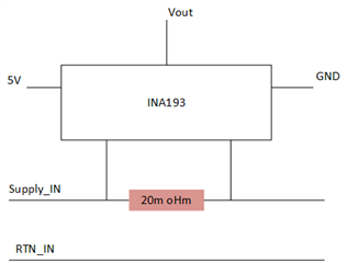
Is this connection right ?
There is no data on isolation between ground, except CMR (data show 80dB).
Best Regards,
Yossi
Hello Yossi,
Thank you for your post. I would like a little bit more information on your application.
What is the application requirement driving the need for separate grounds?
What are the expected voltages for Supply_IN and RTN_IN?
What is the expected current through the 20mΩ shunt resistor?
Best Regards,
Joe
Hi Joe,
I have a system with seperated ground. Supply_In and RTN_In driven 18-36V and I expect max current of 3.5-4A that would go through INA193.
after that it connect to Isolated DC/DC and the output ot the DC/DC make the main gorund.
Best Regards,
Yossi
Hello Yossi,
I need a full schematic to understand what grounds are connected where.
Please provide a schematic where all connections to the GND and RTN_IN nodes are highlighted.
Thank you,
Joe
Hi Joe,
See Attach schematic.
Please see how this all connect, I worried about the isloation between this gnd beacuse INA193.
Best Regards,
Yossi
Thank you Yossi,
Is the output signal of the INA193 being fed to a microcontroller?
Best Regards,
Joe
Hi Joe,
Yes.
My question is if the GND connection is right ?
I am worried that the current that need to measured is "float" beacause it have another GND.
Best Regards
Yossi
Hello Yossi,
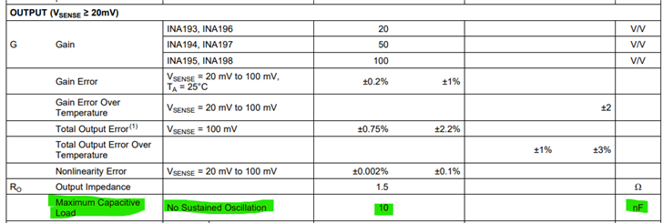
I would like you to try to remove the C2 1uF output capacitor. This is a very large output capacitor and and this can cause oscillations.
For sense voltages greater than 20mV, the maximum capacitive load is 10nF. Your design is operating in the 70mV to 80mV range for Vsense.
Please let me know if this experiment with removing C2 works for you.
Best Regards,
Joe
Hi Joe,
C2 is optional for me. I can remove it or put something else.
I want to get back to my main issue, the GND connection is good ? I would get isolation between the GND and RTN ?
Yossi
Hello Yossi,
I would suggest a smaller cap for C2 as I have said in my previous post.
The grounding should not be a problem as long as the input voltages (voltage between IN+/IN- and GND) are within the limits specified in the datasheet.
Best Regards,
Joe