This thread has been locked.

If you have a related question, please click the "Ask a related question" button in the top right corner. The newly created question will be automatically linked to this question.

LMP2012: Offset Voltage change over the full temperature range.

Part Number: LMP2012
Other Parts Discussed in Thread: LMP2021

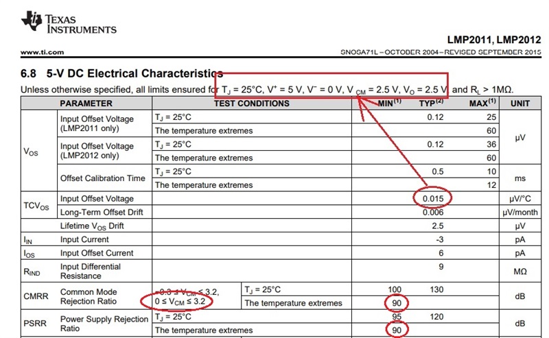
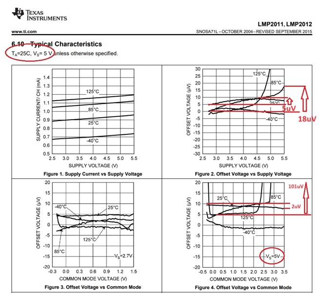
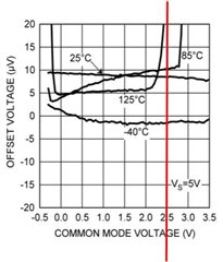
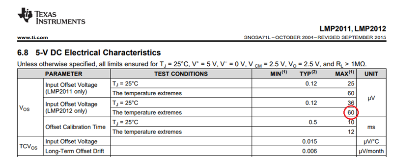
The LMP2012 shows a TCVIO of 0.015 μV/°C.  However, figures 2 through 4 seem to conflict.  If I use a vertical line for the supply or common mode, it looks like the offset voltage can vary 10uV across temperatures from -40 to 85C.  More if I go to 125C.  This would indicate a TCVIO 5 to 10 times worse than predicted using the 0.015 μV/°C listed when operating across the full temperature range.  What am I missing?

  • Monte,

    There are five components of Vos_total as shown below and you seem to confuse Vos_cmrr (third term) and Vos_psrr (fourth) over temperature with a second term of Vos_drift.

    Vos (first term) and Vos_drift (second term) are specified under fixed conditions for a given Vsupply where Vcm and Vout are at mid-supply - see below. 

    Thus, TCVos applies only under these specific conditions and you may NOT change the Vcm (as in Fig 4) or Vsupply (as in Fig 2).

    Fig 2 below shows 5uV Vos change at 25C over Vsupply change from 2.7V to 5.5V;  Thus, at 25C PSRR=20*log(2.8V/5uV) = 115dB (typ PSRR specified 130dB.

    Fig 2 below shows 18uV Vos change at 85C over Vsupply change from 2.7V to 5.5V;  Thus, at 85C PSRR=20*log(2.8V/18uV) = 104dB (min specified 90dB.

    Likewise, Fig 4 above shows a typical 2uV Vos change at 25C over Vcm from -0.3V to 3.2V;  thus, at 25C, CMRR=20*log(3.5V/2uV) = 125dB while typical CMRR specified above is 130dB - see above.

    The minimum CMRR of 90dB for 0<Vcm<3.2V over temp allows max Vos change of Vos_cmrr = 3.2V/[10^(90/20)] =101uV; thus, the graph in Fig 4 for the offset change with Vcm is well within such minimum limit.

    All in all,  I do NOT see any inconsistencies between the LMP2021 datasheet spec table and its typical graphs.

  • Our circuit will be operating at the same test condition shown in the datasheet with the exception of the T.j =25.  Our junction temperature of the device will change along with our ambient temperature.  Part of the required analysis is to show the error or sensitivity due to temperature changes across our full operating range  (-40°C to +85°C) .  I can calibrate for a fixed input offset voltage, but shifts due to temperature drift are problematic--in part due to the non-linear nature of the connected sensor. 

    To summarize, if I maintain the test conditions (excluding temp) I should be able to use the TCVos.  From 25°C to -40°C:  ΔVos = (-65°C*.TCVos) = -0.975 µV, from 25°C to +85°, it would change ΔVos =9 µV.  A very impressive total shift of less than 2µV across the our temperature profile.  In reality, I hope are operating environment is more benign and our ΔT typically <40 °C.

    I guess I had expected to see this operating test point reflected in a convergence the temperature curves, showing an optimal operating point.  I could draw a vertical operating line on the graph.  For Figure 4, Vcm = 2.5V. (not changing) and Vsupply fixed at 5V.  The remaining information on the graph is the Vos at the different temperatures where the vertical line intersects the curves.  

    From your explanations, this is outside the intent of the these graphs and their 2 dimensional information.  Some additional figure that specifically targeted drifts characteristics outside the test conditions might could be useful.

    Thanks for your help.

  • Monte,

    TCVIO of 0.015 μV/°C is a TYPICAL and NOT maximum Vos drift.  Thus, under the test condition at 25 deg C  (with Vcm=Vout=2.5V on Vs=5V) the max Vos is +/-36uV BUT over temperature range you may expect the max Vos up to +/-60uV - see below. Thus, I would estimate that the drift standard deviation to be +/-0.04uV/C and the maximum drift of +/-0.24uV/C (6-sigma).

  • This is the info I needed.  How stable is this for a given, individual amplifier?   I have the ability to measure my circuit board temperature.  I can do an individual calibration that incorporates the temperature.  This assumes that the offset drift will this be repeatable?   I'm guessing this is where the long-term offset drift may apply.

  • Monte,

    If you perform individual op amp over temp calibration, the drift of each unit will be pretty repeatable. As far as the long-term shift of the offset drift goes, without getting into too much detail, statistically speaking after 10 years of operation at 25 deg C, the drift of about 95% of all its units should not change by more than 0.08uV/C (2-sigma).