This thread has been locked.

If you have a related question, please click the "Ask a related question" button in the top right corner. The newly created question will be automatically linked to this question.

INA237-Q1: INA237 / Current sense amplifier vs. Automotive reverse battery.

Part Number: INA237-Q1
Other Parts Discussed in Thread: LMP8603-Q1, INA148-Q1

hello,

for automotive efuse with high-side current sense under reverse polarity condition, i anticipate that  input protection diodes on in+/in- , even if supply is protected.


A simple solution is to put a diode / equivalent devices in series from GND pin of device to gnd net, however i think this will introduce some offset from the small VF drop (of course very low as the quiescent current is also low)


Another solution is to increase IN+/- series resistance to several kOhm To significantly limit the input current back thru inputs BAT-


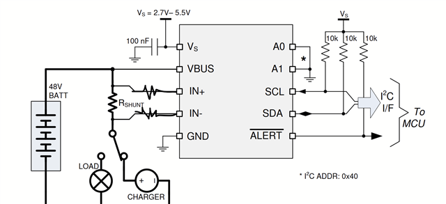
Another option is to use a Opamp with negative CMR capability such as current sense type amp lmp8603-q1 or difference amp (INA148-Q1) which have immunity to this condtion on input.

Thoughts?


  • Hello DJ,

    One other option would be to float the supply of the device to support negative VCMs. Here is an reference design where this is done: https://www.ti.com/tool/TIDA-00313

    Note that if you follow this design to make sure the the digital isolator you use works with the voltage logic levels of the INA you use (and note that many isolators have different specs for each side).

    I do not recommend increasing the series input resistance that high, it would add too much error. 

    I also agree that your first suggestion could add some error as well. 

    Regards,

    Mitch

  • Hi Mitch,

    Thank you for the comments

    Regarding the TI design, I think that may be overkill for our application since we dont have anything powered/measurements during temporary reverse polarity condition. And if we had a GND schottky for RPP i dont THINK we would need a level shifter

    For a schottky in series with GND pin, it wouldn't contribute to error in the current measurement, correct?
    It would, i believe contribute to ~1% or less current error for 12V-24V battery measurement simply because the measurement will be with reference to schottky VF which will be VBAT-VF schottky (which will pobably be <0.2V at such low operating current).

    Considering that, please let me know if the only thing we should see is a small error 1% or less contributed by the schottky to Power and VF.

    We shouldn't have an issue with i2c interface with this small GND offset as well.

    IF thats the case, i can live with that.

    let me know if my thinking makes sense or if you have another suggestion.

    The only thing I can think of besides another difference amplifier for the current sense resistor is to sum the battery measurement + GND offset voltage with a RRIO amp, but that will cost a lot as it requires generating higher voltage than VBAT.

    best

    dimitri

  • Hello Dimitri,

    I think that should be fine, and your logic looks correct for why the error will be relatively small. Just note that all pin voltage specifications and max voltages allowance (such as pins for I2C, address, etc) are rated to the GND pin of the device, which in your case may fluctuate. However, I don't think that will cause any issues. Also note that the communication on the SDA line will not be able to go quite as low either when being controlled by the INA (ie, to device ground not system ground), so make sure that the logic levels are still accepted by your MCU.

    Regards,

    Mitch