This thread has been locked.

If you have a related question, please click the "Ask a related question" button in the top right corner. The newly created question will be automatically linked to this question.

AMC1200: Output noise question

Part Number: AMC1200
Other Parts Discussed in Thread: , AMC1300

Hi,

We built a own evaluation module with the AMC1200 for testing purposes and we encountered more noise than we expected.

The question is, where the noise comes from and if the noise is "normal", so that we just need proper filtering.

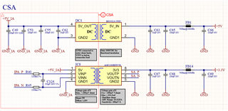
We use an isolated DC/DC converter to produce the AMC1200 input supply of 5V, and that seems to work fine.
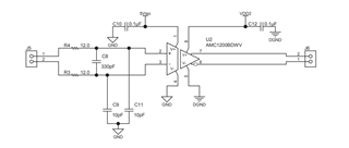
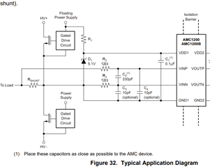
Schematic:

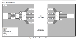
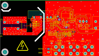
Layout (Note that we have once the GND plane on the input stage under the IP+- traces and once without, but the noise is exactly the same):

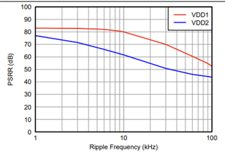
We are measuring the noise with a SMA connector and a short coax cable, so it is definitely not a measurement issue and the noise is the same on all board. Further we supply with a linear low noise power supply that we use a lot for such measurements. The only other candiat for the noise could be the IB0505LS-1WR3, but since the transmission is differential and the AMC1200B has good PSRR, that should not be the problem here.

Note that there is no current through the AMC1200B Input shunt in the following measurements:

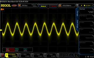
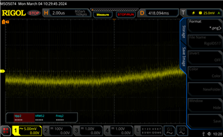
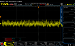
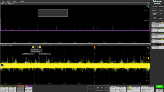
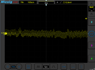
Measurement on VoutN:

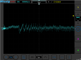
Measurement on VoutP:
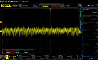
VoutP - VoutN:

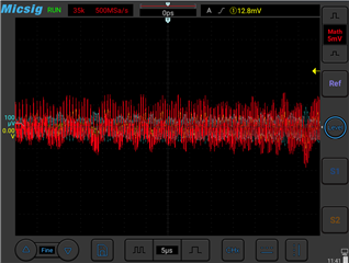
Can you tell me, if this is the normal noise of the AMC1200? In the datasheet it states around 3.1mVrms output noise, which seems to fit with the measurement, but there is also the frequency dependent noise, which should be way less at the frequency we measure now (we are at around 200kHz or even more here)

Edit: I just removed the IB0505LS-1WR3 and the noise is exactly the same, so there when the input side is powered, there comes immediately the noise from the previous measurements.

  • Hi Hans,

    I think this is more noise than we'd expect from the AMC1200.

    In your schematic it doesn't appear you tie VINN to GND1. This should be done to establish the common mode input voltage. Try adding this first and check the results. 

    What does your input look like? Have you probed the input pins of the device? You might add more filtering to the inputs to suppress high-frequency noise. You could also consider adding filtering to the output to dampen ringing effects. 

    Please let me know what you see. 

    Best regards,

    Eva

  • Hi Eva

    The VINN and GND1 are connected together, you cannot see it because I did not show the shunt resistor. You can only see it in the layout above at the shunt left from the amc1200. There is a net tie at the kelvin connection of the shunt, that connects the two together at one point. Am I wrong with that? Should I maybe use bigger traces for the kelvin connection?

    The filtering i can of course adjust, but it is still strange, that it produces so excessive noise, so there must be something fundamentally wrong

    I will do a remeasurement tomorrow of the input

  • Hi Hans,

    Okay, I understand. You did tie VINN to GND1 correctly, but I think you should still try soldering a direct connection between GND1 and VINN when you debug next. The ground plane could be causing some of the noise. Let me know what you see on the input tomorrow and I'll look into what else could be causing the noise. Thank you!

    Best regards,
    Eva

  • Hi Eva

    What do you mean with a direct connection between VINN and GND1? No Kelvin connection for VINN, but directly solder VINN and GND1 together at the IC input pins? 

    In the datasheet, there is a layout recommendation, but it seems not like GND1 and VINN are connected close to the IC and since there are vias, there must be more than one layer used.

    I have to do the input measurements on monday, I am out of office today.

    Thanks,

    Hans

  • Hi Eva,

    I could do again the input noise measurements, but there is no input noise at all (we are directly on the noise floor. The only thing I could see is the supply noise on the VDD1, which has a ripple f +-5mV and some HF switching from the PSU:

    50us resolution:

    2us resolution:

    From the datasheet, the 20kHz ripple should be attenuated by around 73dB, which should be deglictable:

    About the higher frequency switching noise, I don't know if this would be filtered out by the AMC1200. I changed the the power supply to the external linear one and had less ripple and no HF parts, but the output noise waveforms look exactly like in the pictures above. So, I don't think it is an input noise issue and it really looks like the AMC1200 noise is like that.

    I also shorted the input leads out, but there was no change at all in the output noise. When I disconnect VDD1 from the input stage, the noise is gone.

    It would be amazing, if you could test the noise floor internally on a AMC1200.

  • Hi Hans,

    Thank you for getting these figures for me.

    As far as connecting VINN to GND1 directly, we usually do this after the capacitor by drawing a line directly from VINN to GND1. I had thought there could be noise on the input because of the ground plane, but this screenshot you got without that trace looks relatively clean. 

    To confirm, after changing your input power supply, this cleaned up your input further? And after disconnecting your input power supply, the output noise is gone? What does the output look like without power on the input? If you found that removing your power supply eliminated the output noise, possibly we can consider more options for VDD1. Have you looked at the power supply going into the amplifier? Make sure this is stable and free from excessive noise as this can impact output noise. Parallel decoupling capacitors can help.

    The noise floor of the device itself shouldn't be the source, but if you shorted out your input and saw noise that is the noise floor. To reduce the noise floor created, we would still suggest considering your power supply design and grounding strategies. 

    Other considerations could be how long the traces are from your output to your filtering. This is a very long path, where are you measuring output from? The output on VOUTN is odd to me and almost looks like three events which I am curious about. 

    If you think this could be an AMC1200 concern, you could always try replacing the unit with another AMC1200 to confirm if the error is internal to the device or to the system. 

    Please let me know what you try and what results you see. 


     Best regards,

    Eva

  • Hi Eva,

    Thank you for your answer,

    As far as connecting VINN to GND1 directly, we usually do this after the capacitor by drawing a line directly from VINN to GND1. I had thought there could be noise on the input because of the ground plane, but this screenshot you got without that trace looks relatively clean. 

    In the manual of the AMC1200 the VINN is connected to GND1 at the shunt, but not at the filter capacitor. Is this wrongly depicted in the datasheet?

    I did not post a picture of the input noise, because it was on the noise floor (around 300uVrms) of my oscilloscope. The pictures from the last post are from the VDD1 power input.

    To confirm, after changing your input power supply, this cleaned up your input further? And after disconnecting your input power supply, the output noise is gone? What does the output look like without power on the input? If you found that removing your power supply eliminated the output noise, possibly we can consider more options for VDD1. Have you looked at the power supply going into the amplifier? Make sure this is stable and free from excessive noise as this can impact output noise. Parallel decoupling capacitors can help.

    I just switched out the Mornsun DC/DC converter (5mVrms noise), depicted in the initial post, with a lower noise linear PSU, with around 1mVrms noise, but this did not change the output noise at all, also again when shorting the input leads VINP and VINN at the IC. When I disconnect the VDD1 pin ( so the input stage has no power), the output signal is on the noise floor of the oscilloscope. So either the AMC1200 disconnects the outputs when there is no input VDD1 voltage or the noise really somehow comes from the input.

    The noise floor of the device itself shouldn't be the source, but if you shorted out your input and saw noise that is the noise floor. To reduce the noise floor created, we would still suggest considering your power supply design and grounding strategies. 

    The noise floor with 300uVrms should probably be low enough. This is only the noise floor of my oscillosope, in reality it is probably lower.

    Other considerations could be how long the traces are from your output to your filtering. This is a very long path, where are you measuring output from? The output on VOUTN is odd to me and almost looks like three events which I am curious about.

    I would be really surprise if this trace length is already too much (maybe 3cm), especially since we have a differential transmission.

    If you think this could be an AMC1200 concern, you could always try replacing the unit with another AMC1200 to confirm if the error is internal to the device or to the system. 

    I already did, I have 5 boards ready for testing, all with the exactly same behaviour

    Edit: I ordered now also the AMC1200EVM board for verification. Do you have the Altium design files for it? Further, it looks like in the EVM they also use a GND plane on the bottom side (not sure if it is only a 2 layer PCB or not).

    In the EVM board, it looks like GND is not connected to the VINN pin at all, only capacitively coupled:

    But in the datasheet, it is connected together:

  • So, I got the EVM Board and did a reference measurement, it looks like here the AMC1200 produces even more noise than on my own evaulation board. So it definitely seems, that this sensor is as noisy as I measure now. I also used two different oscilloscopes (one handheld in a different environment) with exactly the same result.

    VOUTP:

    VOUTN:

  • Hi Hans,

    I went to the lab to test the AMC1200EVM and got the following results:

    I shorted the inputs and used 5V power supplies. The math scope is the FFT on the positive output and the waveform view shows both the positive and negative outputs. Our measurements show the EVM is within data sheet specifications. We didn't see any noise within the input range (100kHz). 

    If these results do not meet your specifications, you could try using the AMC1300 instead. 

    Best regards,

    Eva

  • Thank you for the measurements